Filter for Electronic Stethoscope

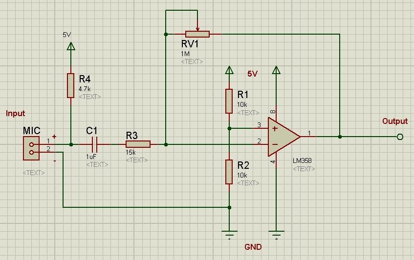
After amplifying the signal that is captured by electronic chest-piece, we get a noticeable amount of noise with the main signal. Most of these are high-frequency ambient noises. Therefore, it becomes a mandatory task for us to design a filter circuit to remove those noises. There I implemented a bandpass filter circuit with the help of ANALOG DEVICE FILTER WIZARD Tools.

As the body sounds those a physician needs to listen lies between 20Hz to 1000Hz [reference], we need to make a bandpass filter that ranges between 20Hz to 1000Hz. And to get a clear heart sound, we added another bandpass circuit (20Hz to 200Hz) in parallel with previous one. Since the heart sounds lie between 20Hz to 200Hz [reference].
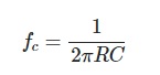
However, an electret microphone can’t capture sounds below 10Hz and human’s hearing frequency is above 20Hz, so we don’t need to be concerned about filtering noise below 20Hz. Therefore, we optimized our circuit by implementing two lowpass filter. The first one which of cutoff frequency 1KHz and the second one cutoff frequency at 350Hz.

Two Low-pass filters. 1KHz cutoff at the top and 200Hz cutoff at the bottom.

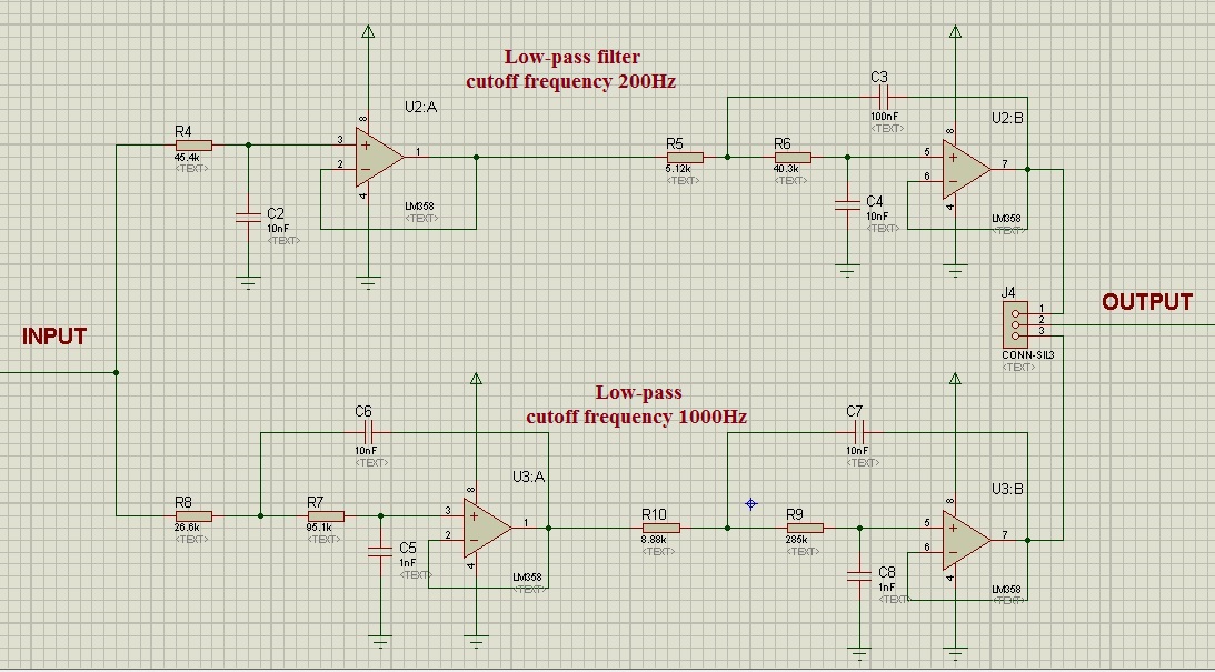
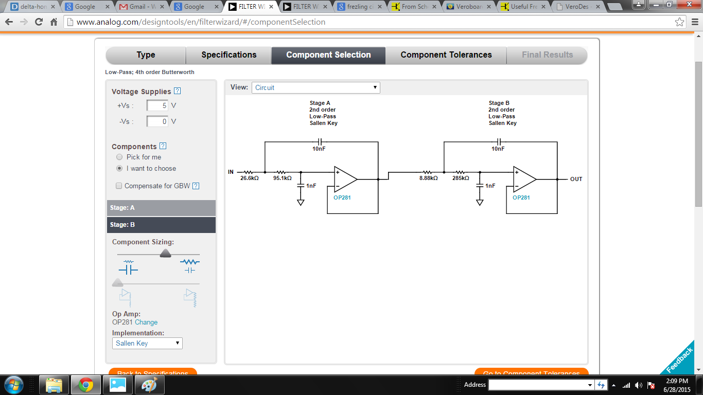
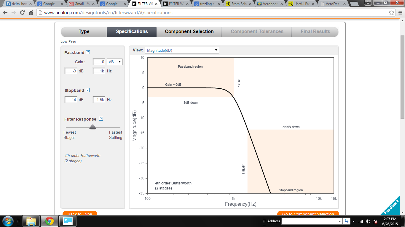
Low-pass (1KHz cutoff) 4th order Butterworth  filter: 

Circuit:

1KHz Fc, Low-pass 4th order Butterworth

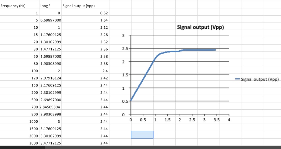
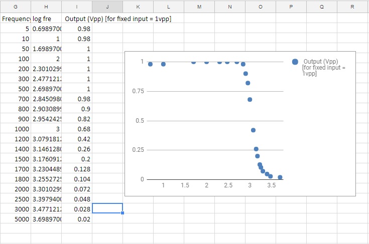
Characteristics and Frequency response:

Frequency response of 1KHz Fc 4th order Low-pass filter


Frequency Response of the Filter, Fc = 1KHz

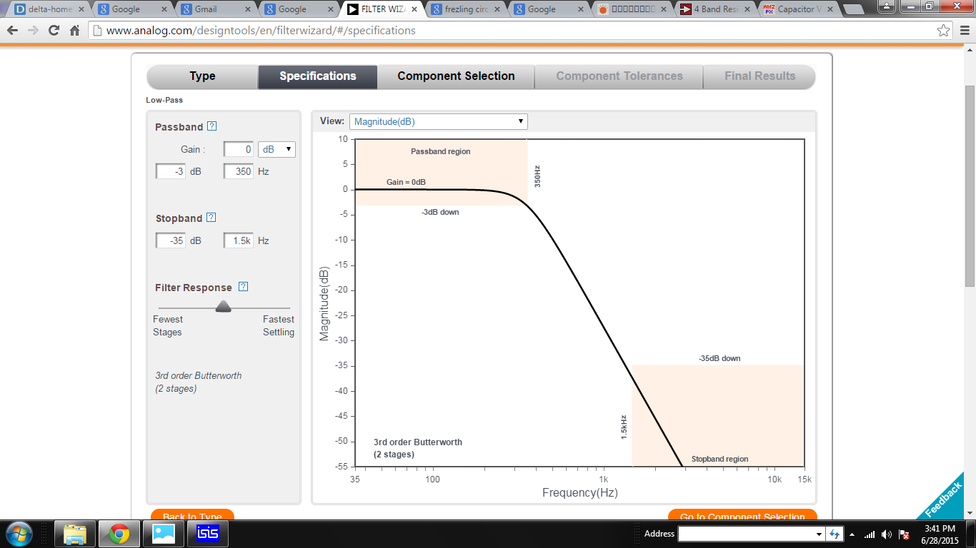
Low-pass (200Hz cutoff) 4th order Butterworth  filter:

Circuit:

350Hz Fc Low-pass Filter

Characteristics and Frequency Response:

Frequency Response of the 350Hz Fc low-pass filter

Two filters get the same input signal simultaneously but we placed a switch at the output end to get the specific filtered signal.

A video will be uploaded there.
A simulation of the low-pass filter circuit on Proteus will be found there.

Pre-amplifier for Electronic Stethoscope

Here, I’m going to show a simple pre-amplifier circuit that I designed for my electronic stethoscope.

This circuit was designed in 2014
Pre-amplifier circuit

This is a single-supply inverting amplifier circuit with a gain of almost 70 times. The circuit is based on op-amp LM358.

From the left side, an Electret microphone is used with a bias resistor R4. This resistor provides an operating voltage of around 1.5V to the microphone. After that, a DC blocking capacitor was used. This capacitor is a must but the value could be chosen by calculating the gain and filter of this amplifier circuit. The resistor R3 and RV1 are the input and feedback resistor of this amplifier circuit. R1 and R2 give a 2.5V at the non-inverting terminal of the op-amp (Pin-2 of LM358), this was done so, to get a 2.5V offset voltage at the output end. The explanation of this will be found in the video below.

Gain =  (feedback resistor / input resistor)  = RV1/R3

As a capacitor was used with a resistor in series, a high pass filter was formed after microphone connection. The cutoff frequency of this filter could be calculated using this formula.

For this circuit, I required Fc = 10Hz. So I kept capacitor value fixed that was 1uF and then calculated the required resistor value for this purpose and got 15K approximate. My gain requirement was 100 times, therefore I chose higher value variable resistor that was 1MΩ. One thing is noted in LM358’s datasheet they recommended not to use feedback resistor value above 1.5MΩ.

Frequency Response of the Pre-amplifier


An excellent explanation of operational amplifier could be found in this video.


Datasheet:
Electret microphone: http://www.cui.com/product/resource/cma-4544pf-w.pdf 
LM358: http://www.ti.com/lit/ds/snosbt3i/snosbt3i.pdf 

Electronic Stethoscope

Stethoscope – an instrument usually used for listening to the heart and lung sounds and measuring the blood pressure of a human or animal. It is also a symbolic tool for doctors or Nurse. Keeping this tool with you means you are a medical professional.

Generally, Acoustic stethoscopes are the most commonly used stethoscope types, in this stethoscope, the sound is captured by a chest piece and transmitted via air-filled hollow tubes to the listener’s ears. Despite its widespread use, the biggest limitation of it is its sound intensity is very low. Therefore it becomes difficult for an elderly doctor who has less hearing power to listen and understand the sound. An excellent solution to this problem could be found through Electronic Stethoscope.
Electronic Stethoscope converts the auscultatory sounds into electrical signals and then does amplification and filtration for better listening.
Electrical Stethoscope could increase the volume of the sounds, could filter the unwanted noise and could visualize the audio signal in digital format (which is called phonocardiogram). However, since the electronic stethoscopes are expensive, it is not being used widely yet.

Constructions:
There are many ways of making electronic stethoscope. To capture sounds, some use piezoelectric crystal, some capacitive sensor. Here, We have used a microphone as it is a very cheap and an easy to implement.

At first, we brought several stethoscopes available in our market. Then we tested their quality, acoustic response, sound intensity, etc. And found that in consideration of price, Littmann classic 2m is best among them.

To make it electronic stethoscope, we first cut the rubber tube 1.5 inch behind the chest-piece. A microphone is soldered with cable and 3mm audio jack and then place it into a plastic casing. Then we put this microphone casing inside the rubber tube of chest-piece. After that, we covered the whole joint with a heat-shrinkable sleeve.

This type of construction is very easy and cheap. We have tested the performance of this stethoscope at our biomedical physics lab and found a satisfactory result. I have uploaded a sound file here for anyone who wishes to listen the recorded sound.


Smart Switch / WiFi Switch / Home Automation Device/ Smart Home Switch / IoT Switch – Control your home appliances using smart phone.

What if you enter your room and, by getting your presence, your room light turns on, your AC/Fan start running. What if you outside your home suddenly remember that you did not turn your room lights off while leaving your home and you want to turn it off now.  What if you are lying in bed and so tired but you forgot to turn your lights off while going to bed. Or you are such a sick that you are not able to leave your bed but you need to increase your fan speed and fan control box is mounted on the wall. If you face any of these situations and want to make your life easier, then there is a device for you. I have made a device that can control your home appliances by taking your command from your smartphone.


Here, I’m calling it Smart Switch Device though there is no AI (Artificial Intelligence) system running on it at this moment. But I have a plan to make it smart when I add voice control options, weather detection, human presence detection at the room, etc.

This smart switch device is mounted on the wall and is connected to the main power line, lights, fan or other home appliances. When the device is on the running mode it creates a wifi hotspot. The users have to be connected their phone to this wifi station. And then using their phone browser then have to log into the internal web server of the device, a control panel will appear in the browser – you will see three on-off keys and speed control bar. Pressing this keys and bar you can turn your lights on and off and can control your fan speed.


Applications:

  • Lights ON/OFF
  • Light dimming
  • Fan ON/OFF speed control
  • Any kinds of home appliances that rated below 250W.

Features:

  • Four devices (Light/Fan) manually ON/OFF using toggle button
  • Three lights and one Fan speed control or light dimming
  • WiFi enables. can be connected to the internet through a router.
  • Control and monitor light/Fans using smartphones that are connected to the same networks. Your phone is your remote control. So don’t need extra remote control.
  • Control and monitor lights/Fan from anywhere in the world by logging into our web server.
  • Password protective secure internal web server.

Electrical Characteristics:

  • Power: AC 220V 50Hz
  • Max Load: 200W
  • Best for Light and Fan
  • Not suitable for Electric iron, heater or heavy loaded machines.

Constructions:

  • Block Diagram
  • Software Architecture

Timeline of the development: 

  • 1st Experiment:  In this experiment, I made only two wifi On/OFF switch. The circuits were very simple used only an esp8266 module and two transistors for switching, two optoisolators, and two TRIACs BT 134 and a 5Volt mobile phone charger. I mounted it near my bed room’s switch panel with necessary electrical wiring. It has been working very smoothly for almost a year. Operating current consumption is below 200mAh and temperature production is around 40°C.  
Made in December 2016
Cuircit


Built-in Web Server
  • 2nd Phase: 

  • 3rd Phase:


  • dddf