Power Amplifier for Electronic Stethoscope

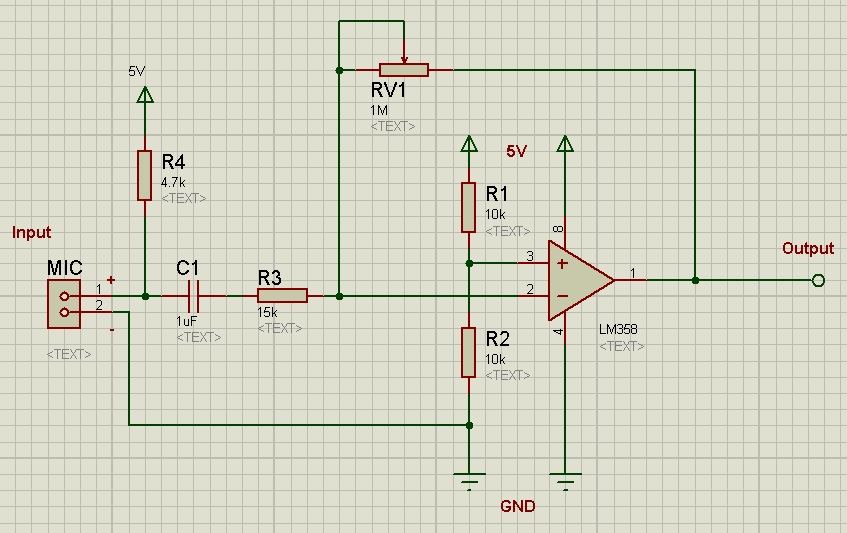
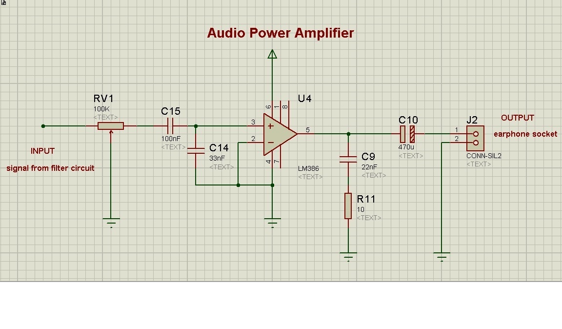
The first stage of the electronic stethoscope circuit was Pre-amplifier and at the second stage filter circuits. In both the stages, op-amp LM358 was used to perform the amplification and filter task. We were supposed to connect an earphone socket at the end of the filter output so that we can insert an earphone to hear the stethoscope sound. But LM358 op-amp can’t provide enough power to drive the earphone. The reason we find is the impedance mismatch between op-amp output impedance and earphone impedance.According to maximum power transfer theorem, maximum power is achieved when the source impedance (here output impedance of the op-amp) is equal to the load impedance (earphone impedance). Since the output impedance of an op-amp is low so it can’t provide enough power to the high impedance earphone (typically, mobile earphone 16Ω to 32Ωand speaker 300 to 600Ω ). To solve this problem, We chose to use an IC name LM386 which is a low voltage audio power amplifier. And it is the 3rd stage of our electronic stethoscope circuit. For this stage, the circuit we designed was based on an example given in the datasheet.

Audio Power Amplifier


Some useful link:
1. Why is impedance matching important? https://www.quora.com/Why-is-impedance-matching-important
2. Understanding Earphone / Headphone Specifications http://www.shure.com/americas/support/find-an-answer/understanding-earphone-headphone-specifications
3. https://en.wikipedia.org/wiki/Maximum_power_transfer_theorem
4. What is the importance of impedance in earphones or speakers? https://www.quora.com/What-is-the-importance-of-impedance-in-earphones-or-speakers

Pre-amplifier for Electronic Stethoscope

Here, I’m going to show a simple pre-amplifier circuit that I designed for my electronic stethoscope.

This circuit was designed in 2014
Pre-amplifier circuit

This is a single-supply inverting amplifier circuit with a gain of almost 70 times. The circuit is based on op-amp LM358.

From the left side, an Electret microphone is used with a bias resistor R4. This resistor provides an operating voltage of around 1.5V to the microphone. After that, a DC blocking capacitor was used. This capacitor is a must but the value could be chosen by calculating the gain and filter of this amplifier circuit. The resistor R3 and RV1 are the input and feedback resistor of this amplifier circuit. R1 and R2 give a 2.5V at the non-inverting terminal of the op-amp (Pin-2 of LM358), this was done so, to get a 2.5V offset voltage at the output end. The explanation of this will be found in the video below.

Gain =  (feedback resistor / input resistor)  = RV1/R3

As a capacitor was used with a resistor in series, a high pass filter was formed after microphone connection. The cutoff frequency of this filter could be calculated using this formula.

For this circuit, I required Fc = 10Hz. So I kept capacitor value fixed that was 1uF and then calculated the required resistor value for this purpose and got 15K approximate. My gain requirement was 100 times, therefore I chose higher value variable resistor that was 1MΩ. One thing is noted in LM358’s datasheet they recommended not to use feedback resistor value above 1.5MΩ.

Frequency Response of the Pre-amplifier


An excellent explanation of operational amplifier could be found in this video.


Datasheet:
Electret microphone: http://www.cui.com/product/resource/cma-4544pf-w.pdf 
LM358: http://www.ti.com/lit/ds/snosbt3i/snosbt3i.pdf