After amplifying the signal that is captured by electronic chest-piece, we get a noticeable amount of noise with the main signal. Most of these are high-frequency ambient noises. Therefore, it becomes a mandatory task for us to design a filter circuit to remove those noises. There I implemented a bandpass filter circuit with the help of ANALOG DEVICE FILTER WIZARD Tools.
As the body sounds those a physician needs to listen lies between 20Hz to 1000Hz [reference], we need to make a bandpass filter that ranges between 20Hz to 1000Hz. And to get a clear heart sound, we added another bandpass circuit (20Hz to 200Hz) in parallel with previous one. Since the heart sounds lie between 20Hz to 200Hz [reference].
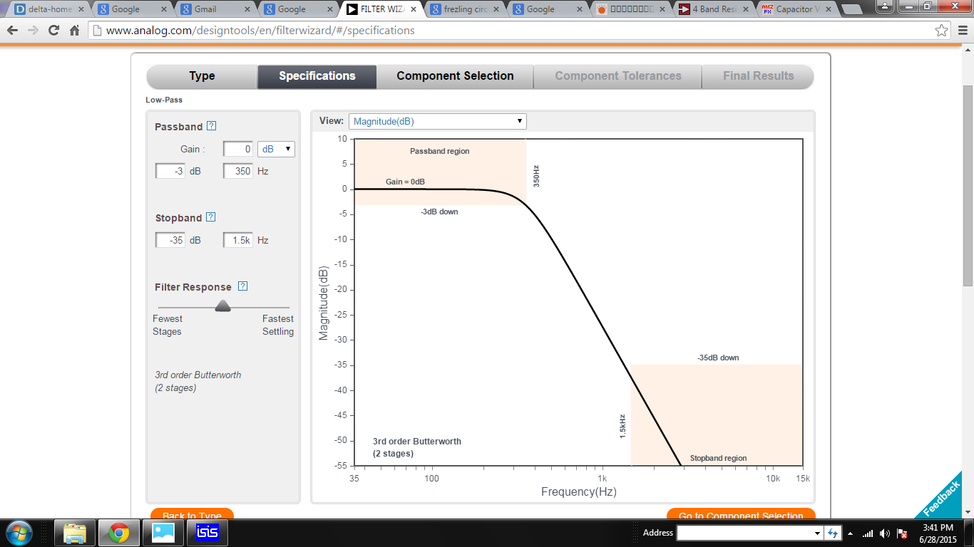
However, an electret microphone can’t capture sounds below 10Hz and human’s hearing frequency is above 20Hz, so we don’t need to be concerned about filtering noise below 20Hz. Therefore, we optimized our circuit by implementing two lowpass filter. The first one which of cutoff frequency 1KHz and the second one cutoff frequency at 350Hz.
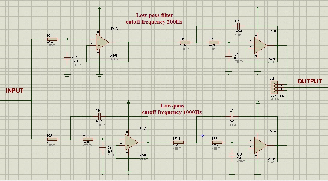
Low-pass (1KHz cutoff) 4th order Butterworth filter:
Circuit:
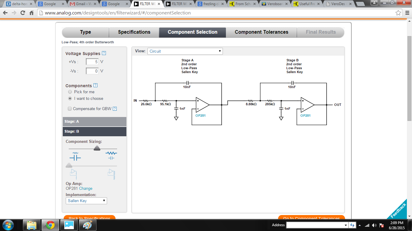
Characteristics and Frequency response:
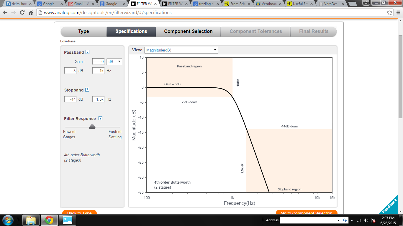
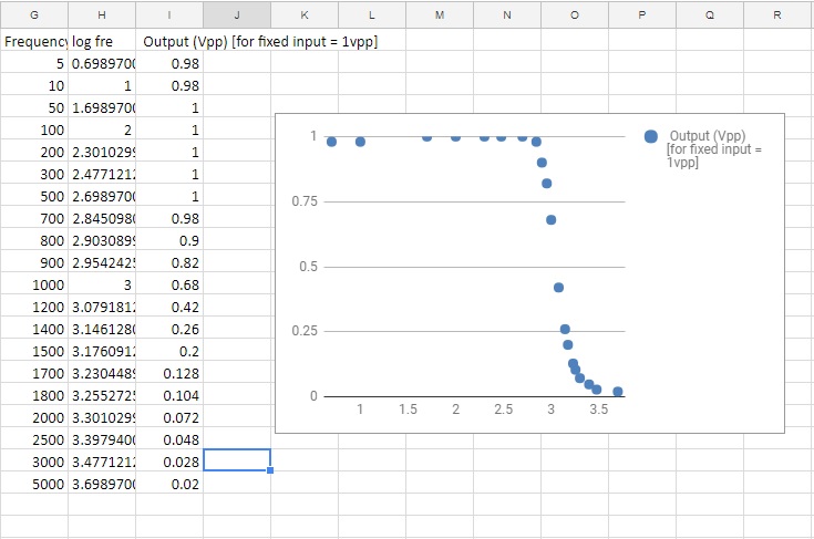
Low-pass (200Hz cutoff) 4th order Butterworth filter:
Circuit:

Characteristics and Frequency Response:
Two filters get the same input signal simultaneously but we placed a switch at the output end to get the specific filtered signal.
A video will be uploaded there.
A simulation of the low-pass filter circuit on Proteus will be found there.