Month: November 2017

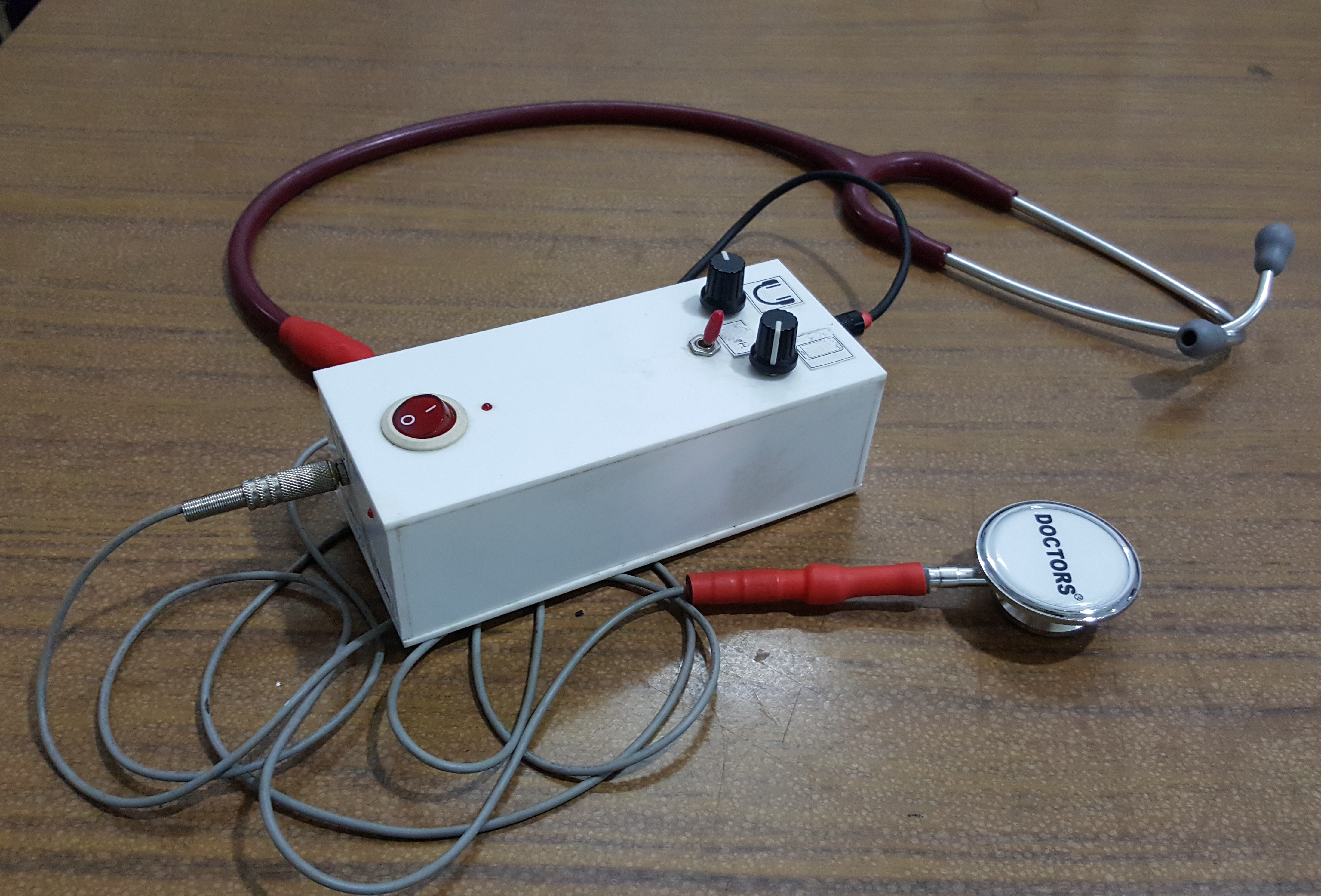
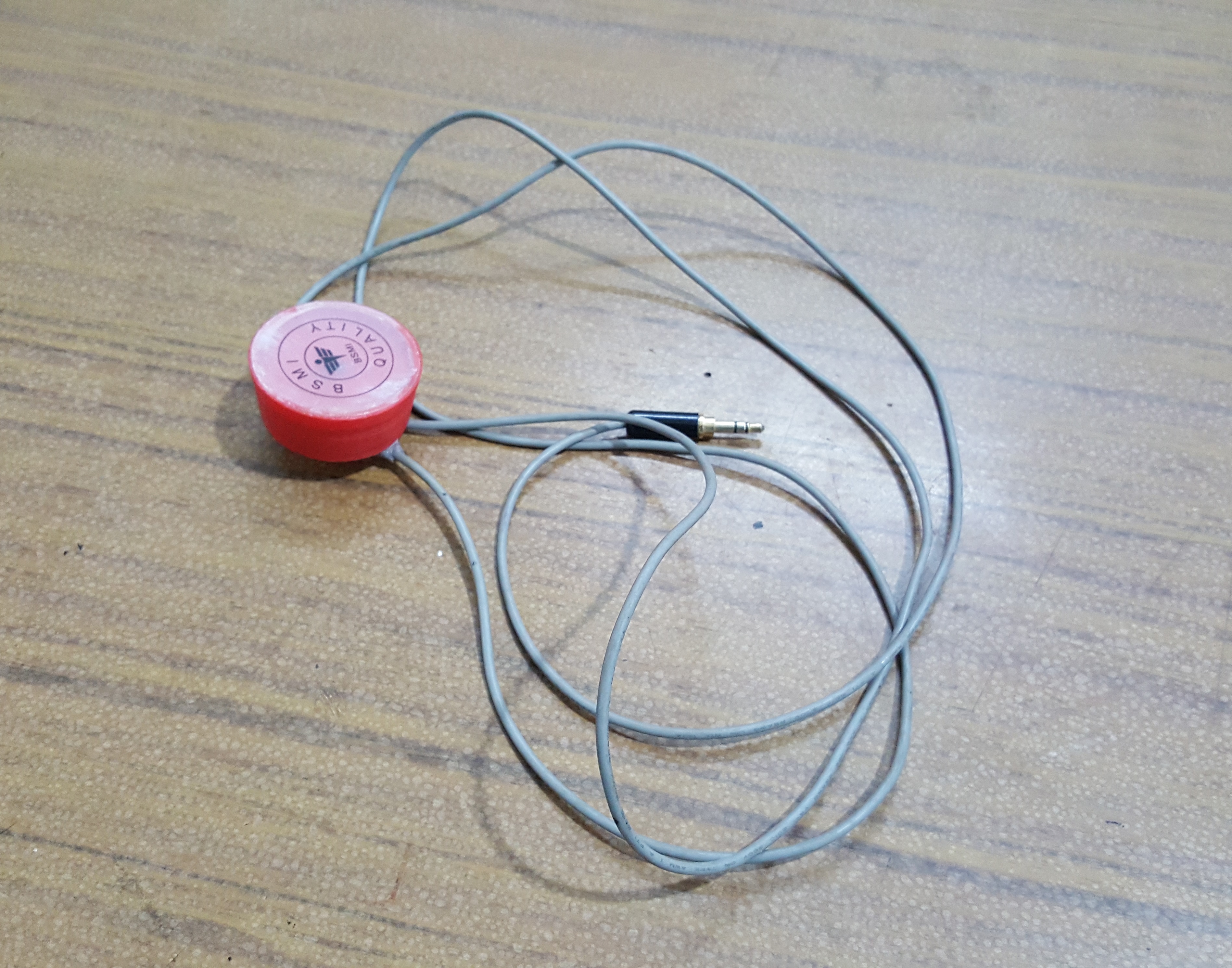
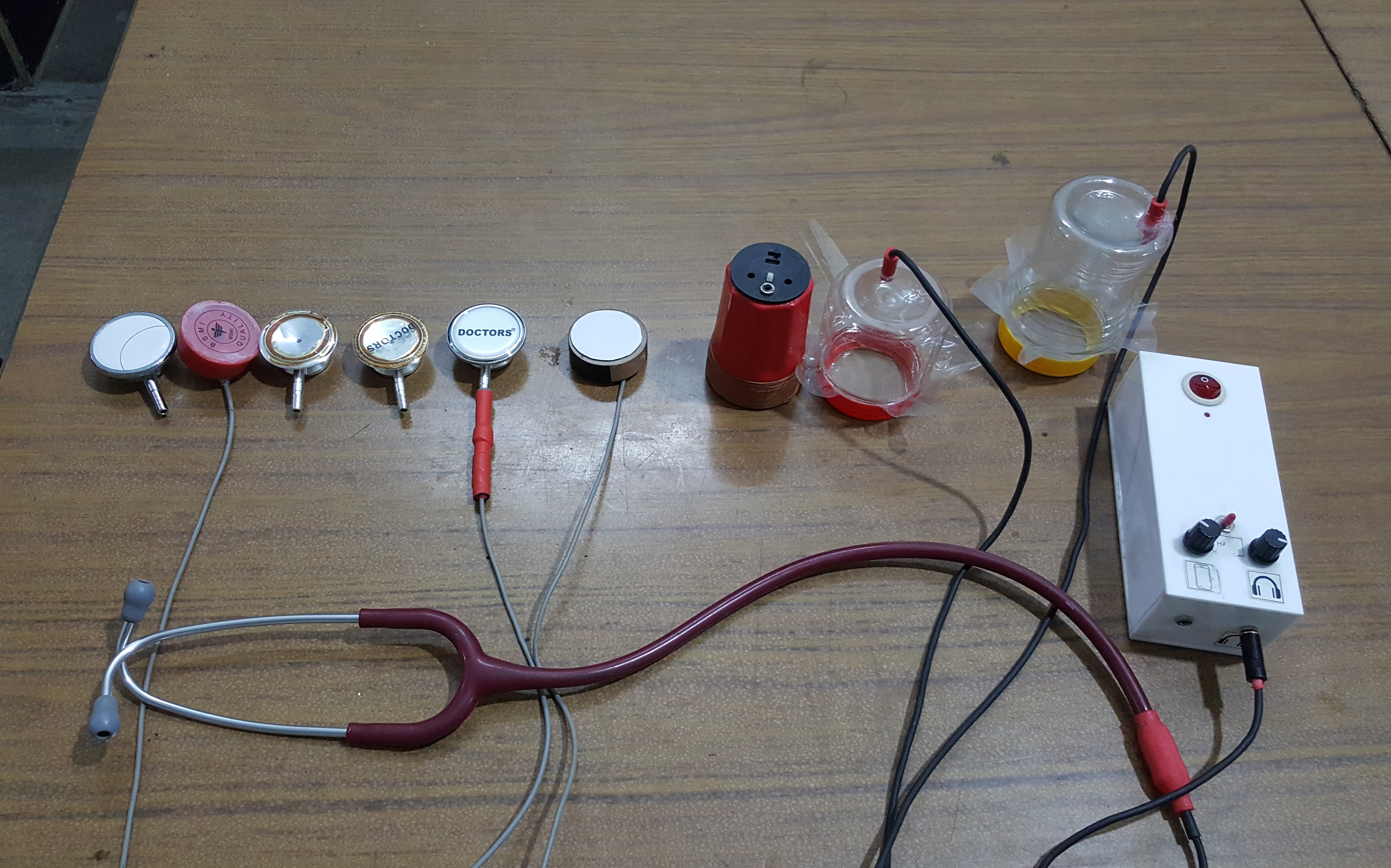
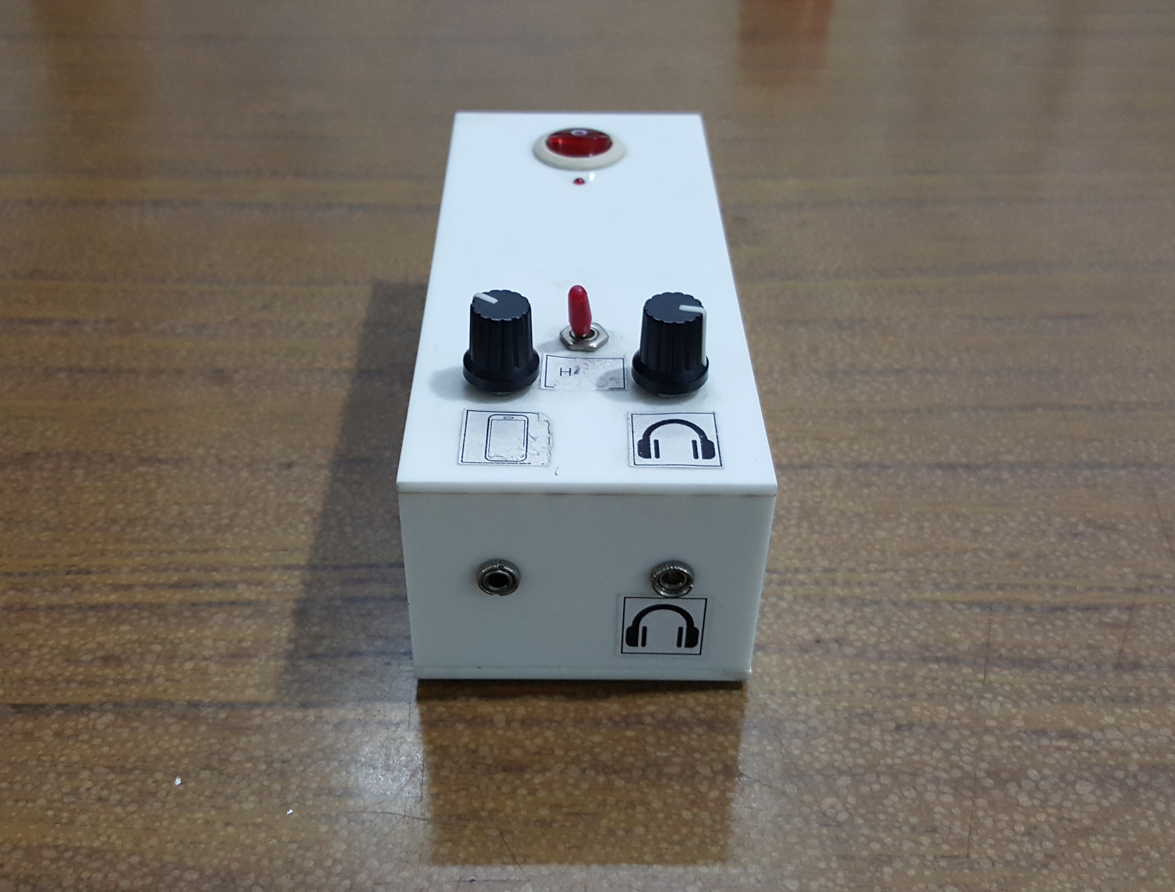
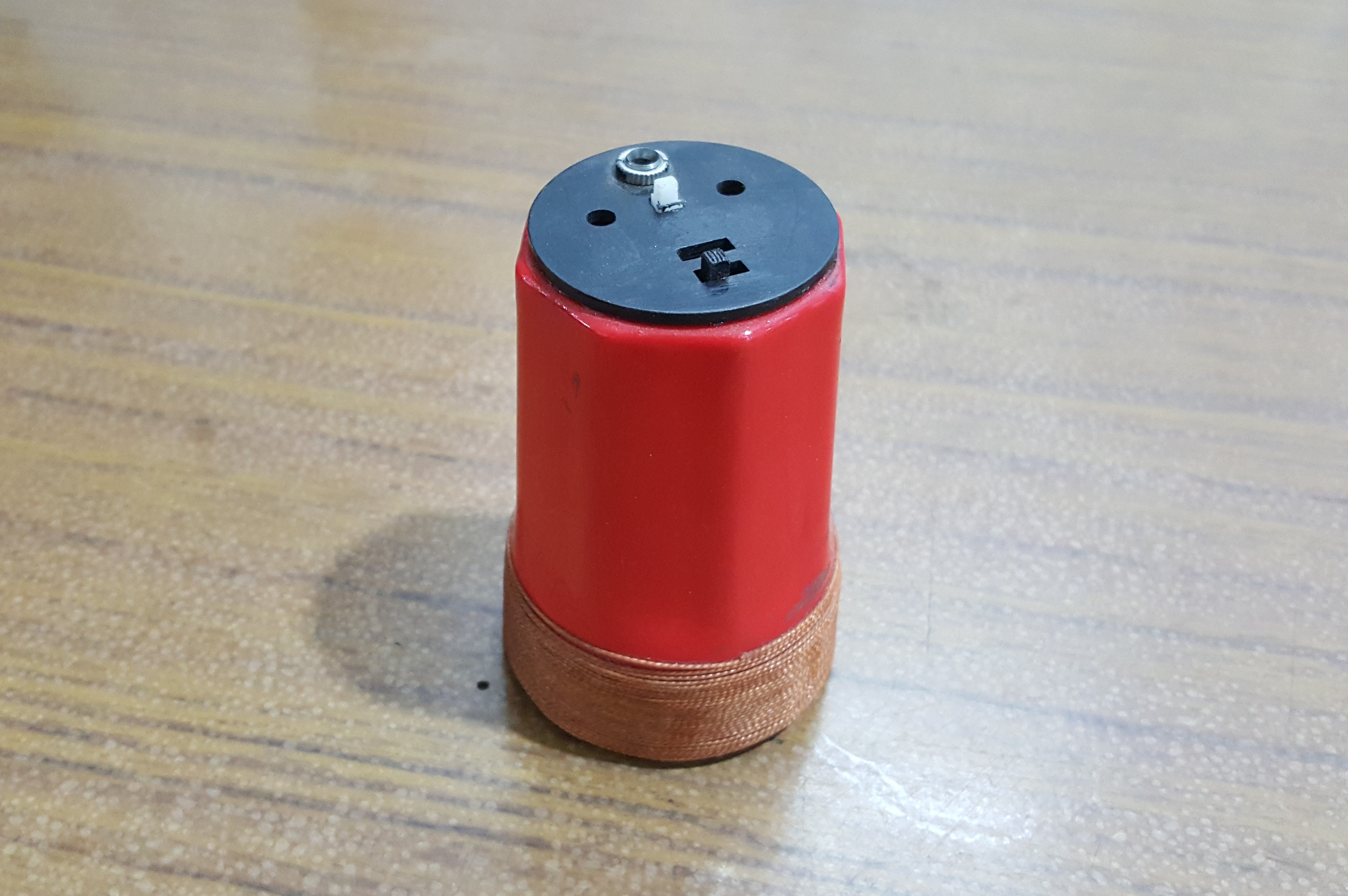
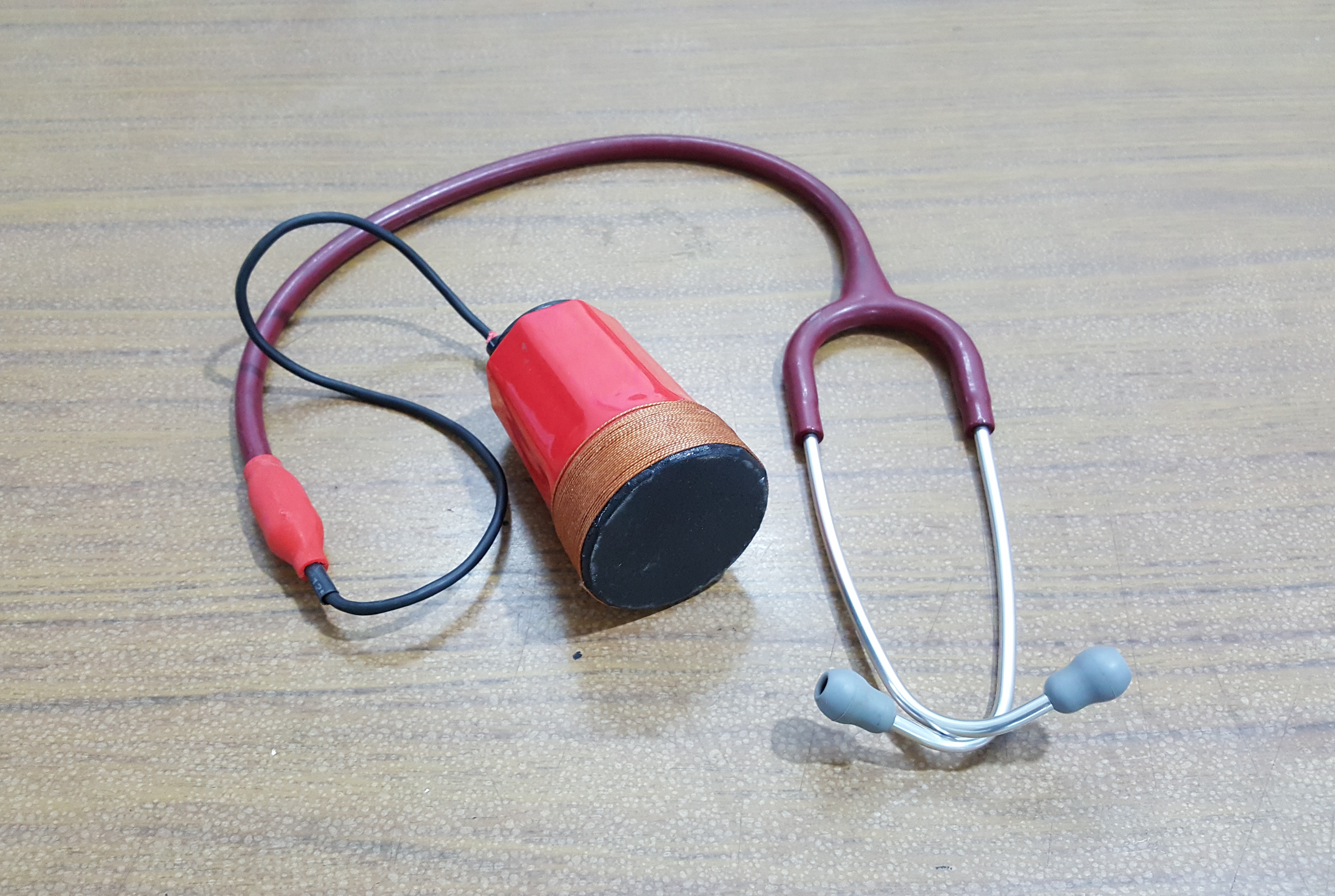
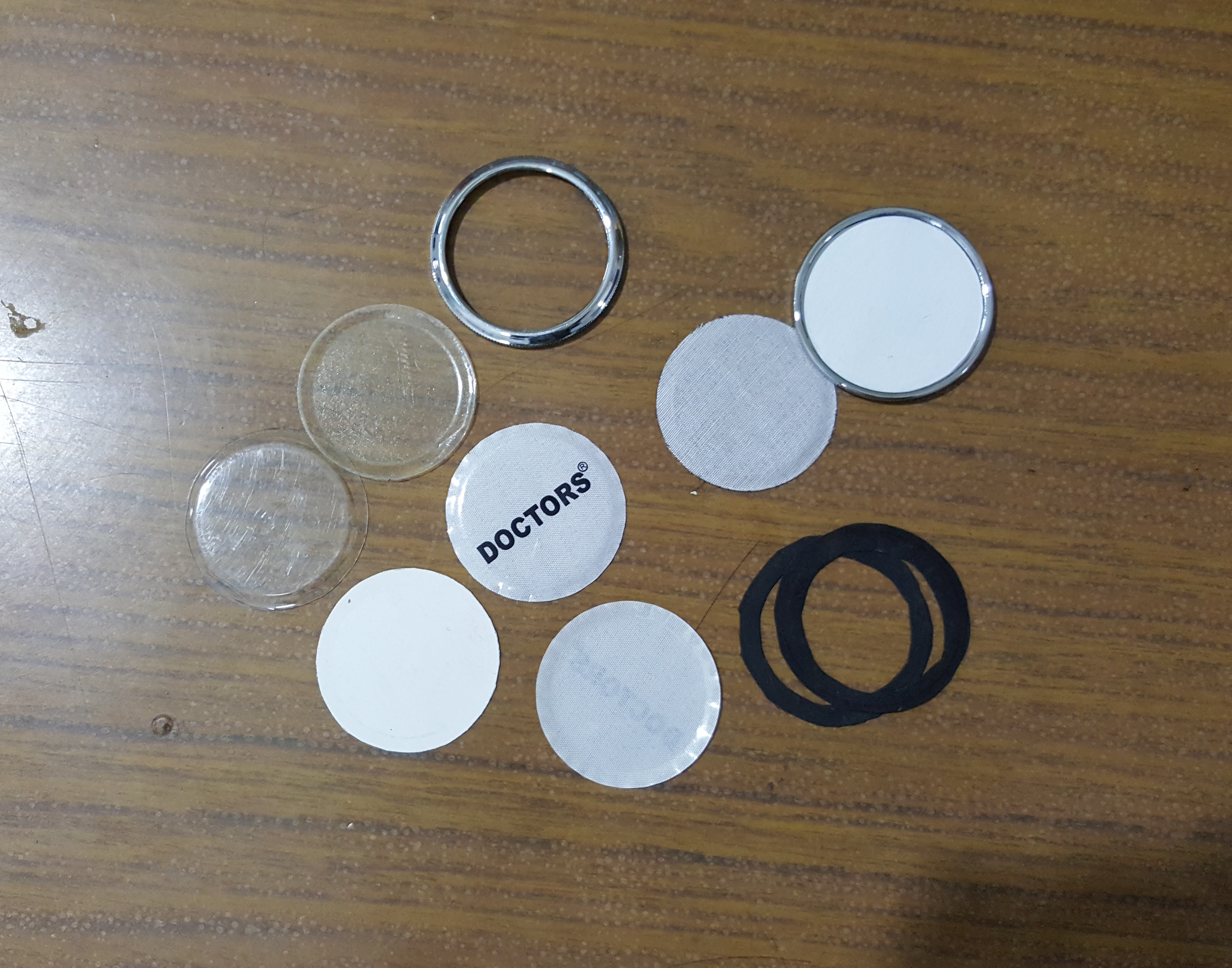
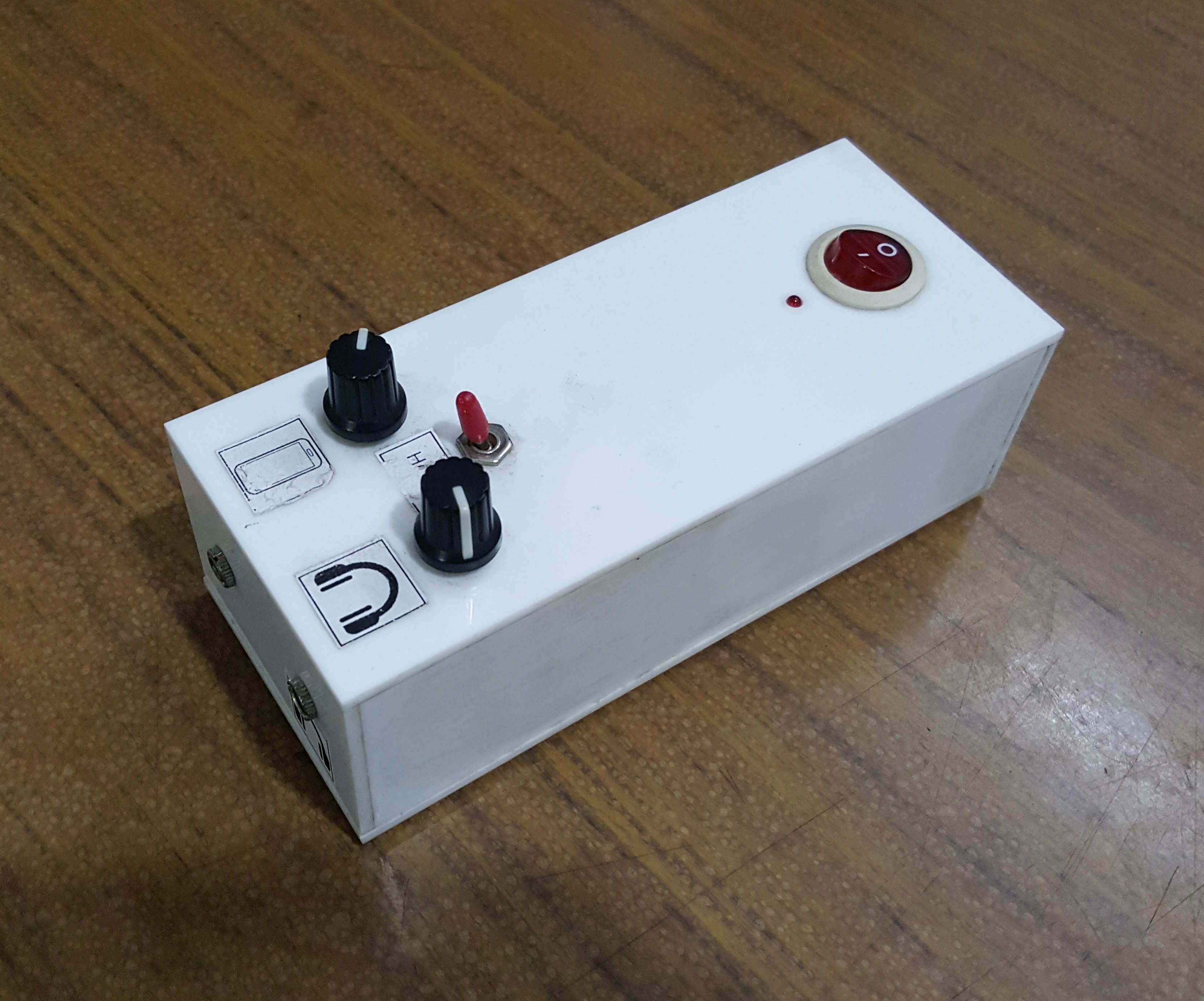
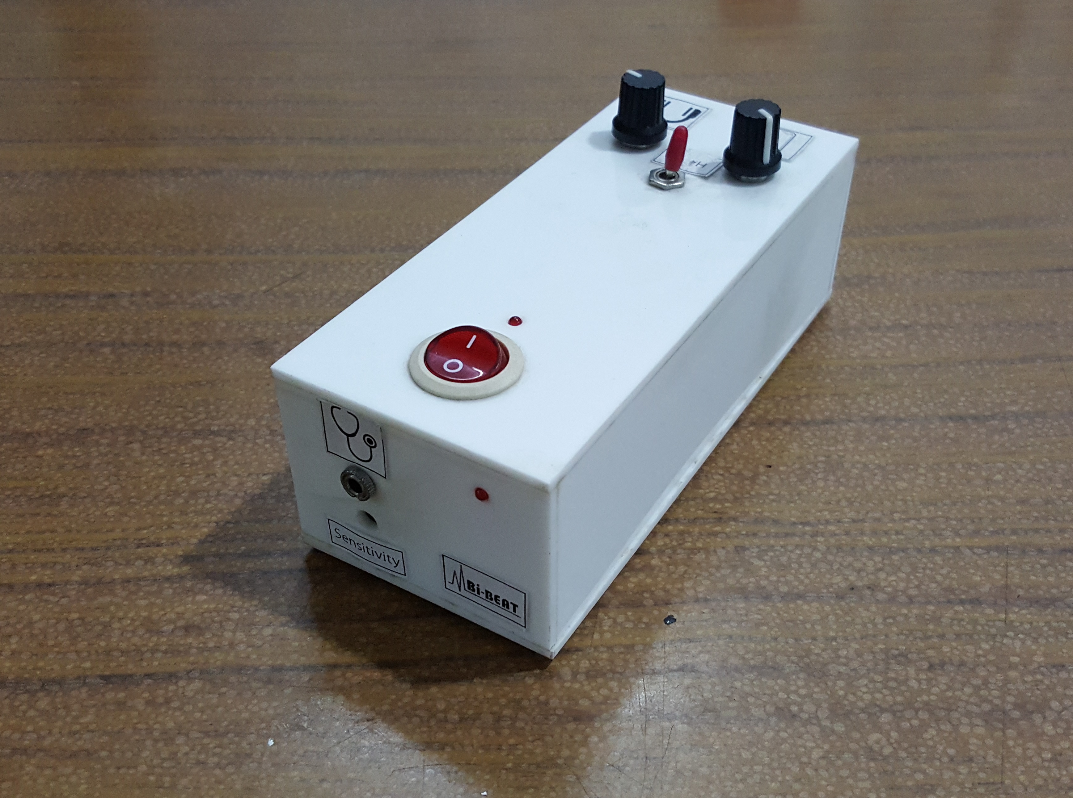
Some prototypes of our Electronic Stethoscope

Filter and amplifier device for Electronic Stethoscope: 

.
.
.
Glass shaped Electronic Stethoscope: 

.
.
.
Electronic Stethoscope amplifier device with chest-piece and earpiece:

.
.
.
3D Printed Electronic Stethoscope chest piece: 

3D Printed Stethoscope Bell

.
.
.
Some other prototypes: 


{ Comments are closed }

Full Circuit of Electronic Stethoscope

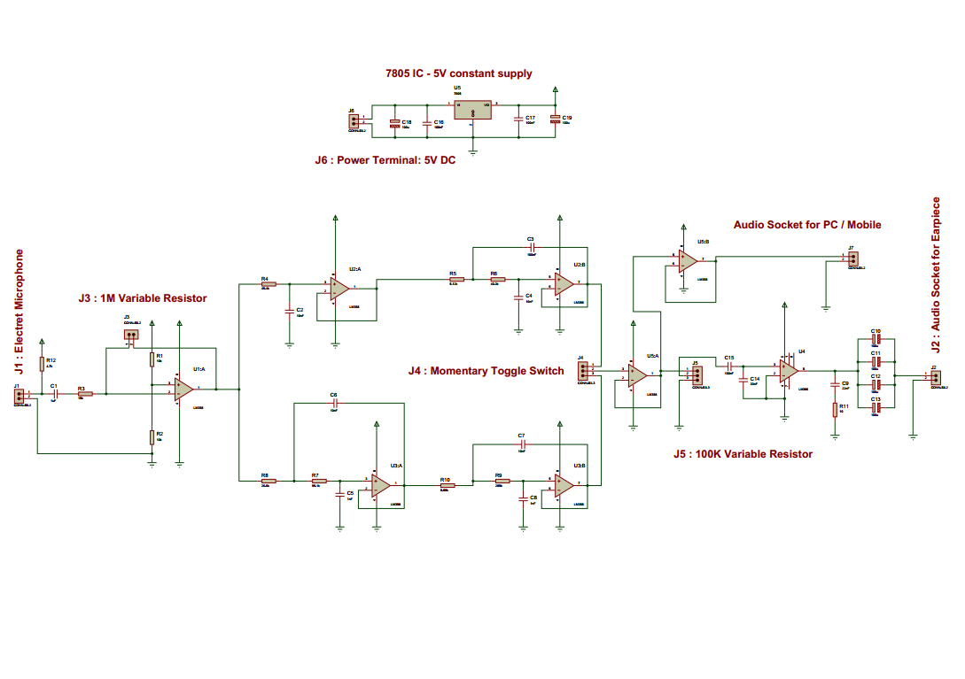
Complete Circuit diagram of our electronic stethoscope is shown below.

Full Circuit Diagram

I discussed every stage of the circuit in my previous posts. Here it just shows the integration of all of the parts and  a constant 5V DC supply circuit (top in the picture) is added.

The overall performance of the circuit:

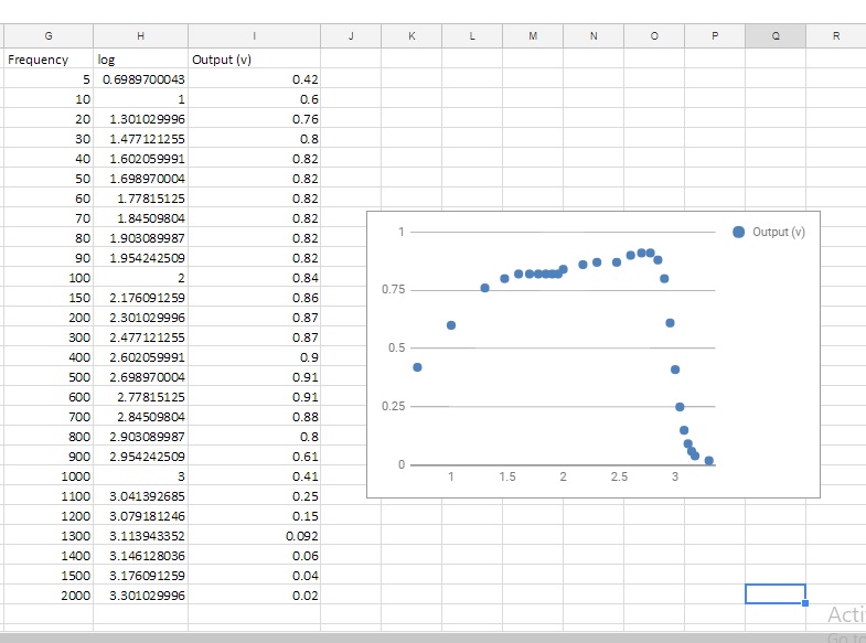
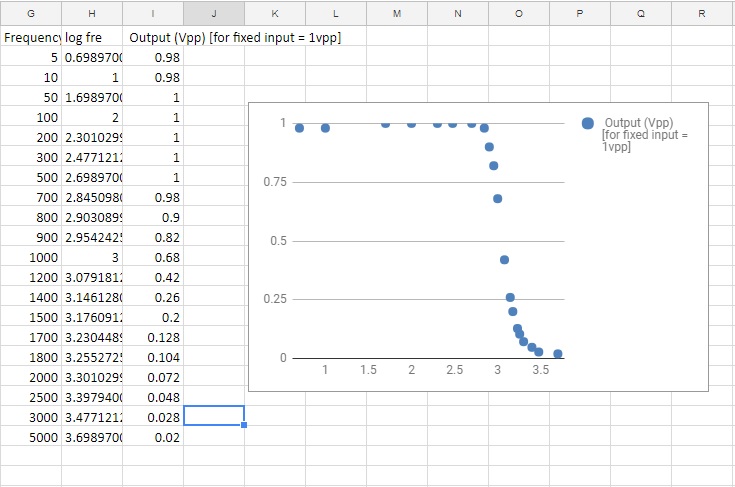
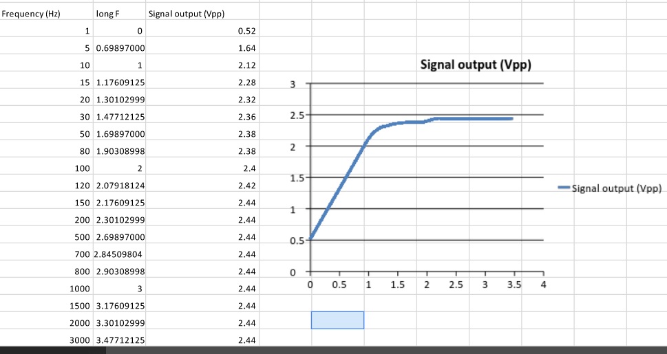
Frequency Response:

Frequency Response of the Overall Circuit

Completed circuit:

Completed Prototype:

The prototype of the Electronic Stethoscope Device.

Recorded sound: with visualization

Schematic diagram and PCB layout:
1. Schematic Diagram
2. PCB Layout 


{ Comments are closed }

Power Amplifier for Electronic Stethoscope

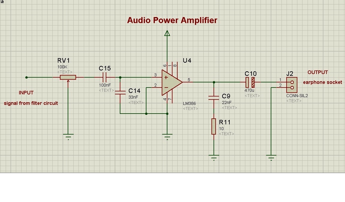
The first stage of the electronic stethoscope circuit was Pre-amplifier and at the second stage filter circuits. In both the stages, op-amp LM358 was used to perform the amplification and filter task. We were supposed to connect an earphone socket at the end of the filter output so that we can insert an earphone to hear the stethoscope sound. But LM358 op-amp can’t provide enough power to drive the earphone. The reason we find is the impedance mismatch between op-amp output impedance and earphone impedance.According to maximum power transfer theorem, maximum power is achieved when the source impedance (here output impedance of the op-amp) is equal to the load impedance (earphone impedance). Since the output impedance of an op-amp is low so it can’t provide enough power to the high impedance earphone (typically, mobile earphone 16Ω to 32Ωand speaker 300 to 600Ω ). To solve this problem, We chose to use an IC name LM386 which is a low voltage audio power amplifier. And it is the 3rd stage of our electronic stethoscope circuit. For this stage, the circuit we designed was based on an example given in the datasheet.

Audio Power Amplifier


Some useful link:
1. Why is impedance matching important? https://www.quora.com/Why-is-impedance-matching-important
2. Understanding Earphone / Headphone Specifications http://www.shure.com/americas/support/find-an-answer/understanding-earphone-headphone-specifications
3. https://en.wikipedia.org/wiki/Maximum_power_transfer_theorem
4. What is the importance of impedance in earphones or speakers? https://www.quora.com/What-is-the-importance-of-impedance-in-earphones-or-speakers

{ Comments are closed }

Filter for Electronic Stethoscope

After amplifying the signal that is captured by electronic chest-piece, we get a noticeable amount of noise with the main signal. Most of these are high-frequency ambient noises. Therefore, it becomes a mandatory task for us to design a filter circuit to remove those noises. There I implemented a bandpass filter circuit with the help of ANALOG DEVICE FILTER WIZARD Tools.

As the body sounds those a physician needs to listen lies between 20Hz to 1000Hz [reference], we need to make a bandpass filter that ranges between 20Hz to 1000Hz. And to get a clear heart sound, we added another bandpass circuit (20Hz to 200Hz) in parallel with previous one. Since the heart sounds lie between 20Hz to 200Hz [reference].
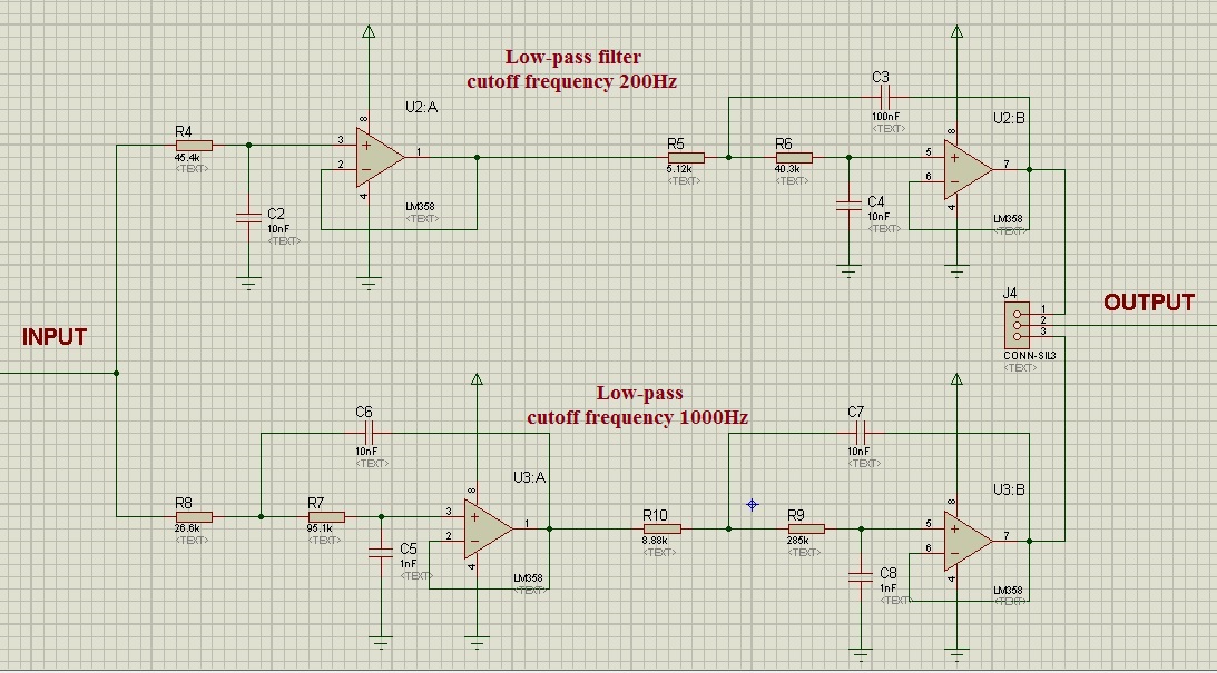
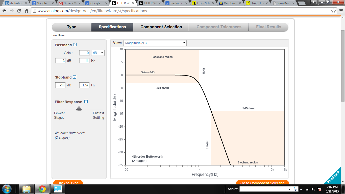
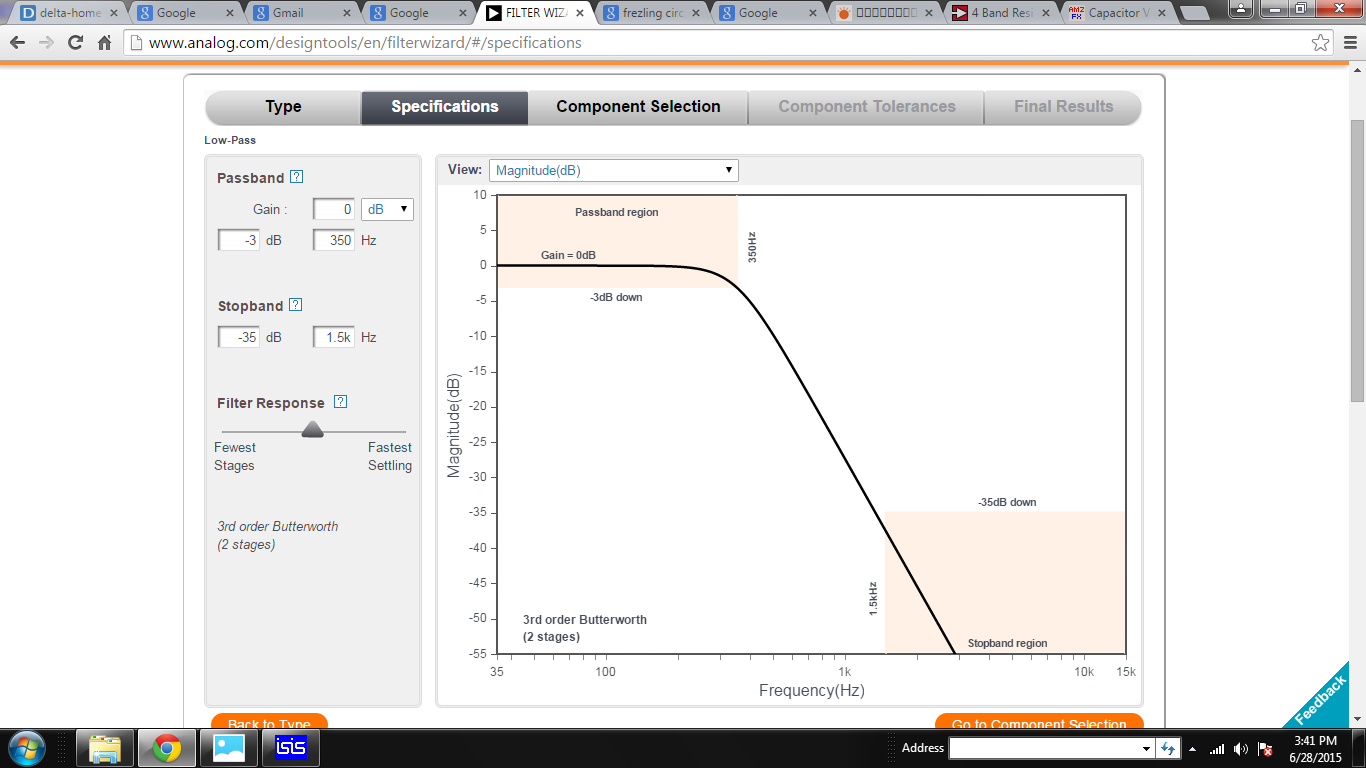
However, an electret microphone can’t capture sounds below 10Hz and human’s hearing frequency is above 20Hz, so we don’t need to be concerned about filtering noise below 20Hz. Therefore, we optimized our circuit by implementing two lowpass filter. The first one which of cutoff frequency 1KHz and the second one cutoff frequency at 350Hz.

Two Low-pass filters. 1KHz cutoff at the top and 200Hz cutoff at the bottom.

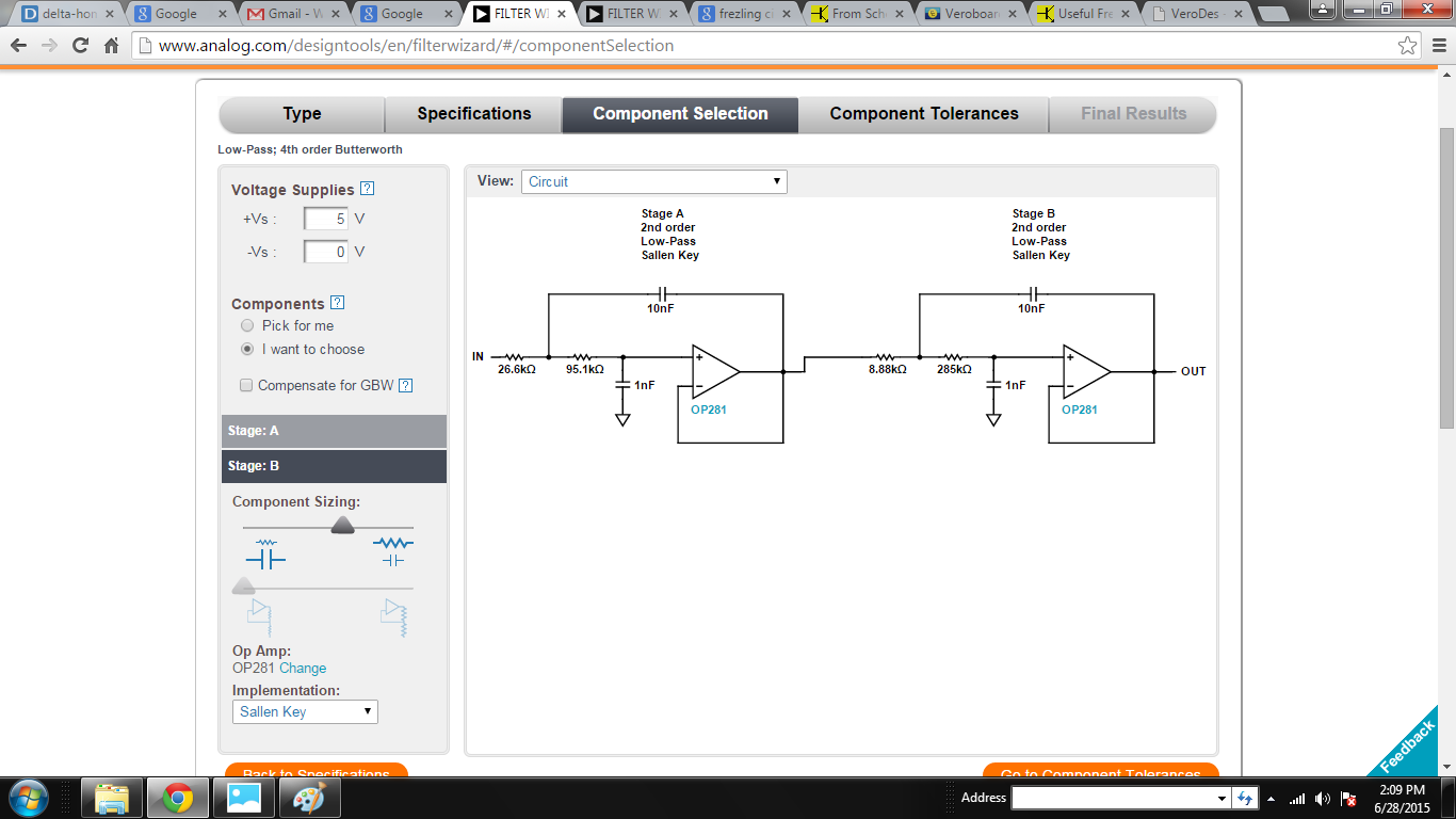
Low-pass (1KHz cutoff) 4th order Butterworth  filter: 

Circuit:

1KHz Fc, Low-pass 4th order Butterworth

Characteristics and Frequency response:

Frequency response of 1KHz Fc 4th order Low-pass filter


Frequency Response of the Filter, Fc = 1KHz

Low-pass (200Hz cutoff) 4th order Butterworth  filter:

Circuit:

350Hz Fc Low-pass Filter

Characteristics and Frequency Response:

Frequency Response of the 350Hz Fc low-pass filter

Two filters get the same input signal simultaneously but we placed a switch at the output end to get the specific filtered signal.

A video will be uploaded there.
A simulation of the low-pass filter circuit on Proteus will be found there.

{ Comments are closed }

Pre-amplifier for Electronic Stethoscope

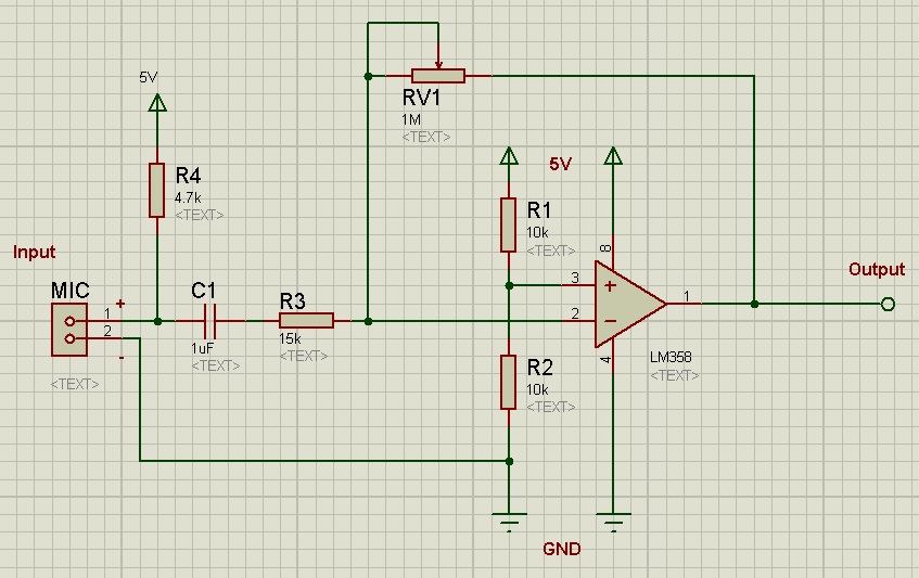
Here, I’m going to show a simple pre-amplifier circuit that I designed for my electronic stethoscope.

This circuit was designed in 2014
Pre-amplifier circuit

This is a single-supply inverting amplifier circuit with a gain of almost 70 times. The circuit is based on op-amp LM358.

From the left side, an Electret microphone is used with a bias resistor R4. This resistor provides an operating voltage of around 1.5V to the microphone. After that, a DC blocking capacitor was used. This capacitor is a must but the value could be chosen by calculating the gain and filter of this amplifier circuit. The resistor R3 and RV1 are the input and feedback resistor of this amplifier circuit. R1 and R2 give a 2.5V at the non-inverting terminal of the op-amp (Pin-2 of LM358), this was done so, to get a 2.5V offset voltage at the output end. The explanation of this will be found in the video below.

Gain =  (feedback resistor / input resistor)  = RV1/R3

As a capacitor was used with a resistor in series, a high pass filter was formed after microphone connection. The cutoff frequency of this filter could be calculated using this formula.

For this circuit, I required Fc = 10Hz. So I kept capacitor value fixed that was 1uF and then calculated the required resistor value for this purpose and got 15K approximate. My gain requirement was 100 times, therefore I chose higher value variable resistor that was 1MΩ. One thing is noted in LM358’s datasheet they recommended not to use feedback resistor value above 1.5MΩ.

Frequency Response of the Pre-amplifier


An excellent explanation of operational amplifier could be found in this video.


Datasheet:
Electret microphone: http://www.cui.com/product/resource/cma-4544pf-w.pdf 
LM358: http://www.ti.com/lit/ds/snosbt3i/snosbt3i.pdf 

{ Comments are closed }

Electronic Stethoscope

Stethoscope – an instrument usually used for listening to the heart and lung sounds and measuring the blood pressure of a human or animal. It is also a symbolic tool for doctors or Nurse. Keeping this tool with you means you are a medical professional.

Generally, Acoustic stethoscopes are the most commonly used stethoscope types, in this stethoscope, the sound is captured by a chest piece and transmitted via air-filled hollow tubes to the listener’s ears. Despite its widespread use, the biggest limitation of it is its sound intensity is very low. Therefore it becomes difficult for an elderly doctor who has less hearing power to listen and understand the sound. An excellent solution to this problem could be found through Electronic Stethoscope.
Electronic Stethoscope converts the auscultatory sounds into electrical signals and then does amplification and filtration for better listening.
Electrical Stethoscope could increase the volume of the sounds, could filter the unwanted noise and could visualize the audio signal in digital format (which is called phonocardiogram). However, since the electronic stethoscopes are expensive, it is not being used widely yet.

Constructions:
There are many ways of making electronic stethoscope. To capture sounds, some use piezoelectric crystal, some capacitive sensor. Here, We have used a microphone as it is a very cheap and an easy to implement.

At first, we brought several stethoscopes available in our market. Then we tested their quality, acoustic response, sound intensity, etc. And found that in consideration of price, Littmann classic 2m is best among them.

To make it electronic stethoscope, we first cut the rubber tube 1.5 inch behind the chest-piece. A microphone is soldered with cable and 3mm audio jack and then place it into a plastic casing. Then we put this microphone casing inside the rubber tube of chest-piece. After that, we covered the whole joint with a heat-shrinkable sleeve.

This type of construction is very easy and cheap. We have tested the performance of this stethoscope at our biomedical physics lab and found a satisfactory result. I have uploaded a sound file here for anyone who wishes to listen the recorded sound.
 

{ Comments are closed }