Complete Circuit diagram of our electronic stethoscope is shown below.
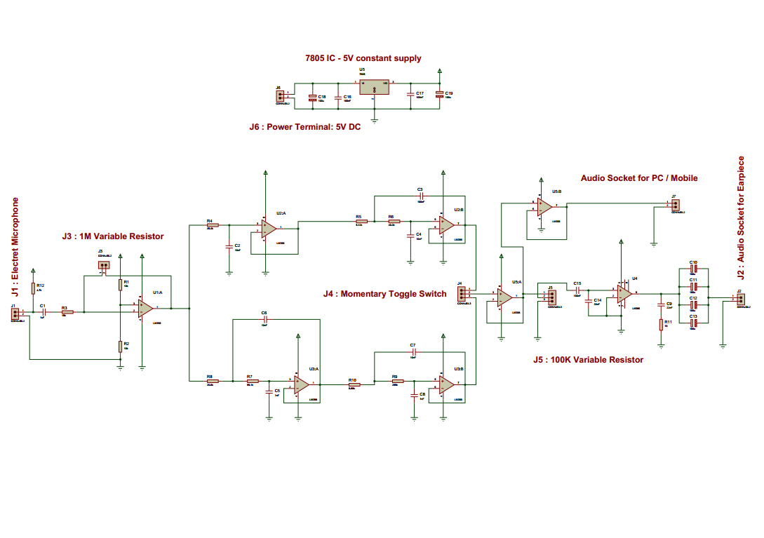
I discussed every stage of the circuit in my previous posts. Here it just shows the integration of all of the parts and a constant 5V DC supply circuit (top in the picture) is added.
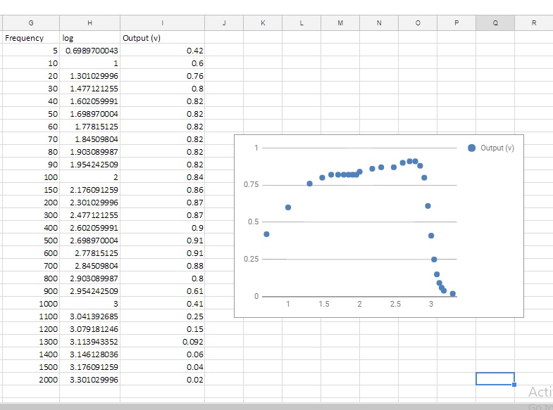
The overall performance of the circuit:
Frequency Response:
Completed circuit:
Completed Prototype:

Recorded sound: with visualization
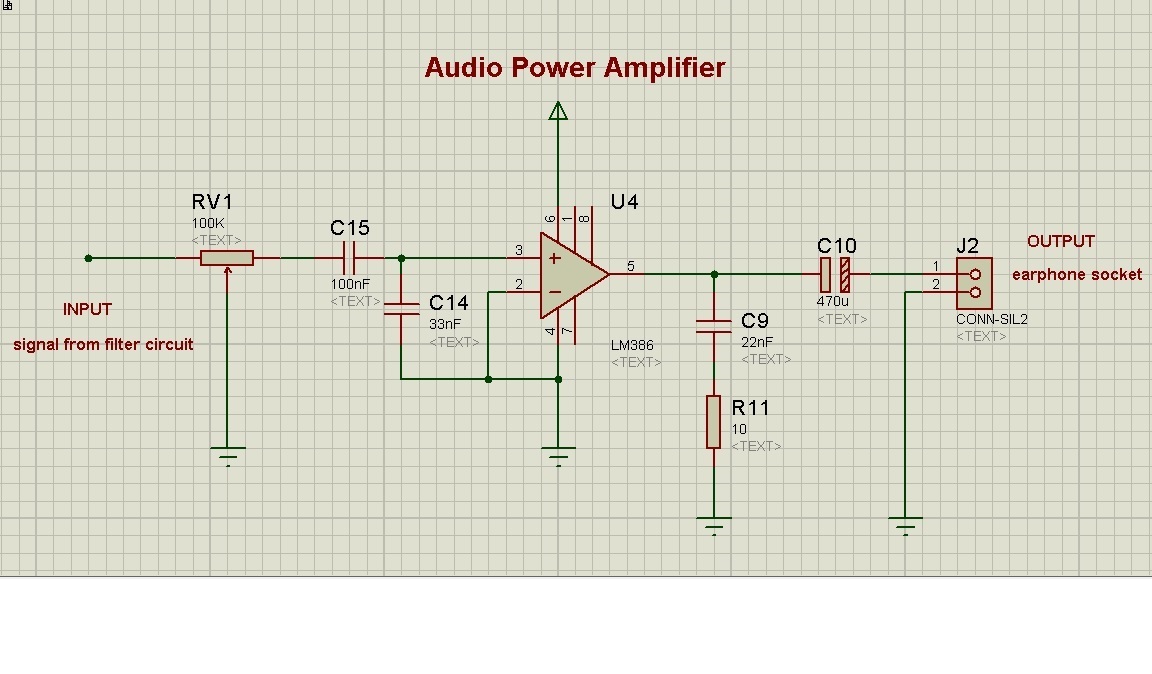
Schematic diagram and PCB layout:
1. Schematic Diagram
2. PCB Layout