Introducing the WiFi IoT Electric Switch: A Leap Towards Smart Home Automation
In 2017, I embarked on an exciting project to develop a WiFi IoT Electric Switch aimed at transforming the way we control electrical appliances such as lights, fans, and other equipment up to 150 Watts. This innovative device enables users to manage and monitor their appliances from anywhere in the world, provided there is an internet connection.
Key Features and Components:
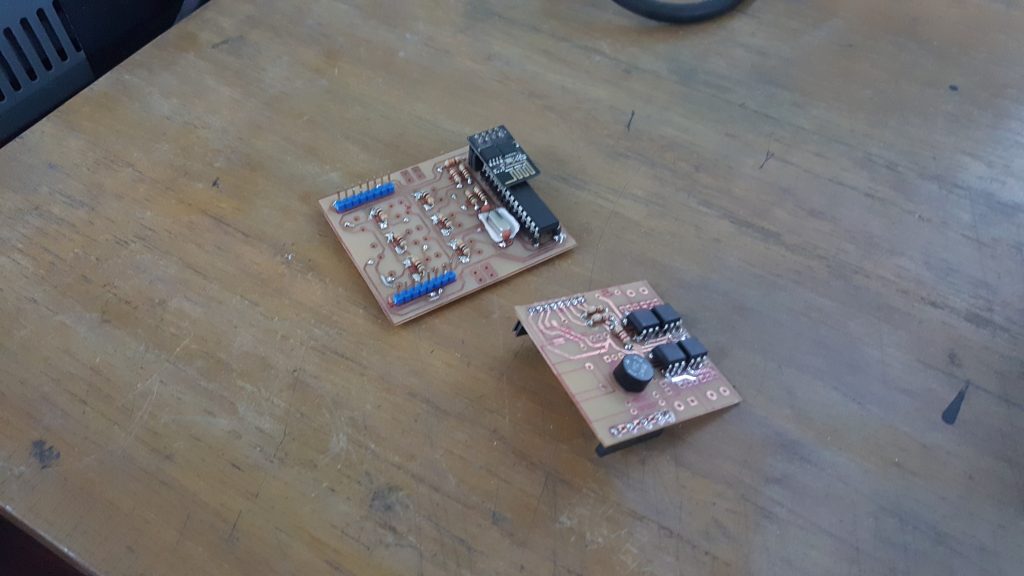
The WiFi IoT Electric Switch is built around the low-cost, highly efficient ESP8266 WiFi module, complemented by the Atmega8 microcontroller. Here’s a breakdown of the major components and their functions:
- ESP8266 WiFi Module: This module provides the device with wireless connectivity, allowing it to interface with the internet seamlessly.
- Atmega8 Microcontroller: Serves as the brain of the switch, managing inputs, outputs, and processing.
- Triacs and Optocouplers: These components are crucial for switching and controlling the electrical loads safely.
- 5V 1A SMPS Power Supply: Ensures that the entire system receives a stable power supply.
For controlling fan speeds and light dimming, the device employs the zero-crossing detection technique, which improves efficiency and performance.
Software and Protocols:
The firmware for the ESP8266 module was developed using the ESP8266-arduino library, which is available at ESP8266-Arduino Library. This library provides a robust foundation for programming the module in a familiar Arduino environment.
Additionally, for handling communication via the MQTT protocol, the device utilizes the ThingsBoard.io IoT platform. This platform offers comprehensive support for IoT device management and data visualization, ensuring a seamless user experience.
Visuals and Demonstrations:
Below are some images showcasing the design and implementation of the WiFi IoT Electric Switch:
- Schematic Diagrams:
- 3D PCB Views:
- PCB AVR Part:
- PCB Switch Part:
- PCB Layouts:
- Final Implementation:
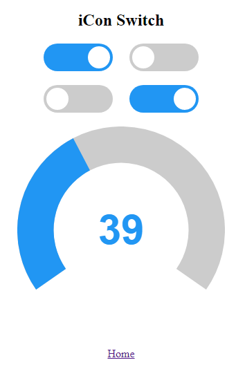
- App Interface and Physical Switch:
- Installed Device:
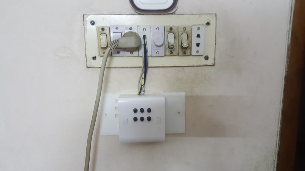
This prototype has been running since 5th July 2018.
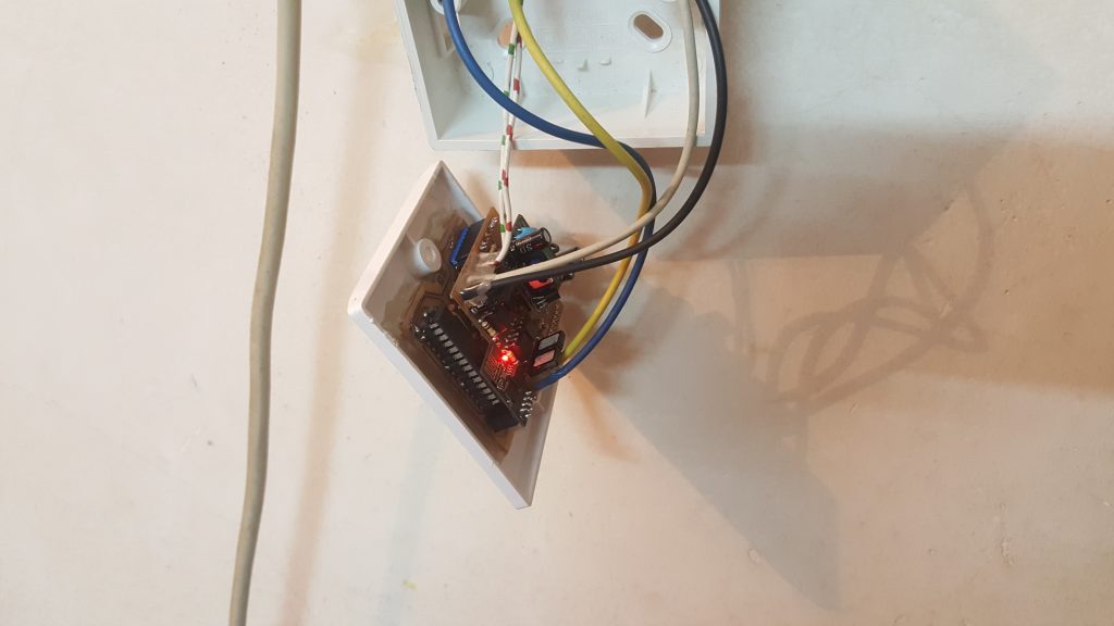
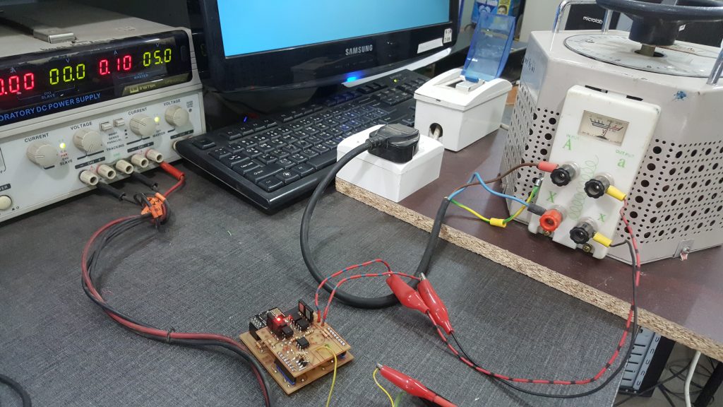
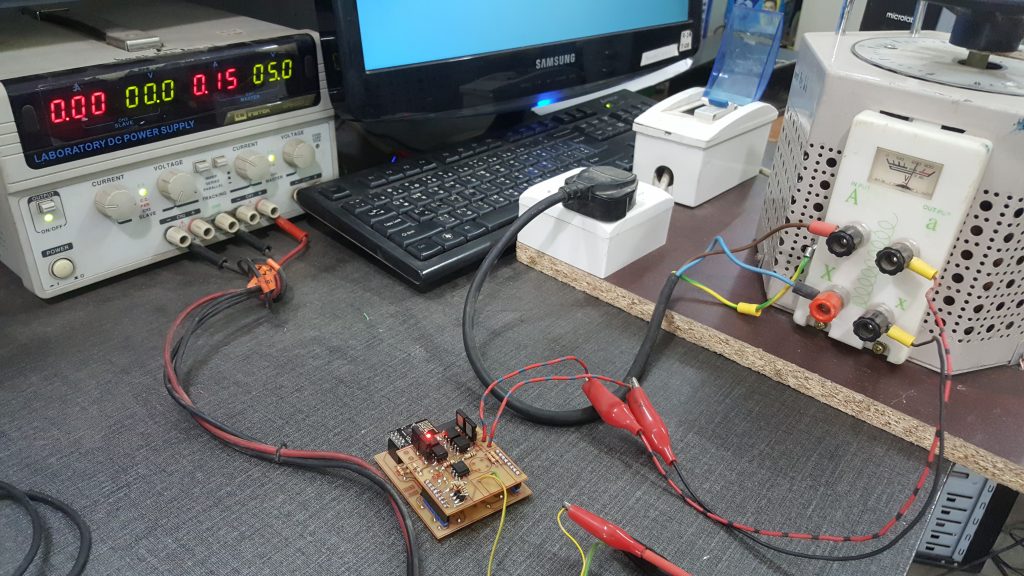
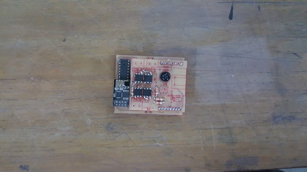
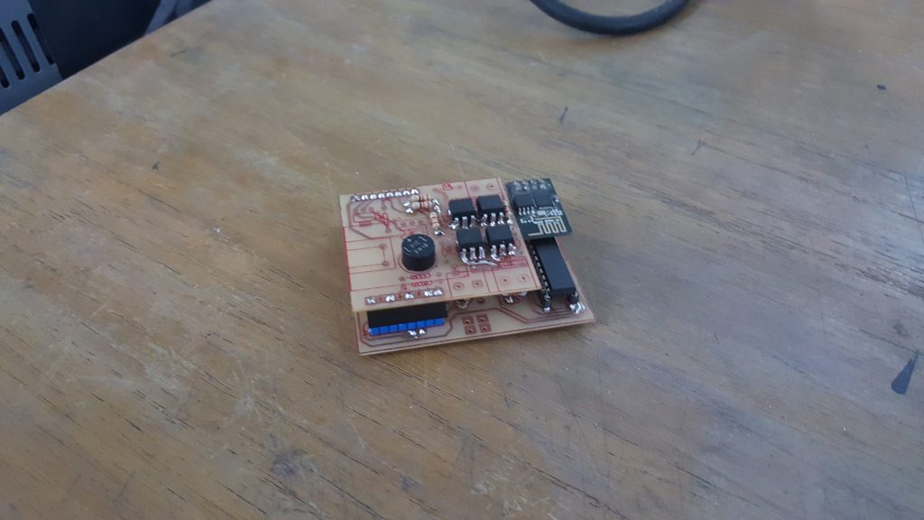
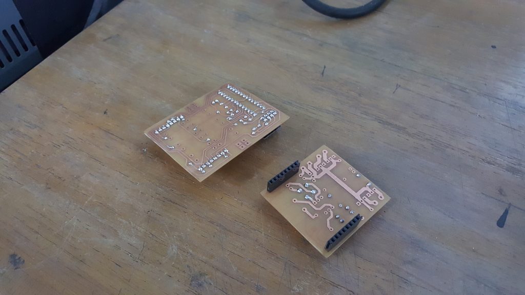
below photos are added on 5.10.2018
![]()


