Month: August 2018

WiFi IoT Electric Switch for Home Appliances

Introducing the WiFi IoT Electric Switch: A Leap Towards Smart Home Automation

In 2017, I embarked on an exciting project to develop a WiFi IoT Electric Switch aimed at transforming the way we control electrical appliances such as lights, fans, and other equipment up to 150 Watts. This innovative device enables users to manage and monitor their appliances from anywhere in the world, provided there is an internet connection.

Key Features and Components:

The WiFi IoT Electric Switch is built around the low-cost, highly efficient ESP8266 WiFi module, complemented by the Atmega8 microcontroller. Here’s a breakdown of the major components and their functions:

  • ESP8266 WiFi Module: This module provides the device with wireless connectivity, allowing it to interface with the internet seamlessly.
  • Atmega8 Microcontroller: Serves as the brain of the switch, managing inputs, outputs, and processing.
  • Triacs and Optocouplers: These components are crucial for switching and controlling the electrical loads safely.
  • 5V 1A SMPS Power Supply: Ensures that the entire system receives a stable power supply.

For controlling fan speeds and light dimming, the device employs the zero-crossing detection technique, which improves efficiency and performance.

Software and Protocols:

The firmware for the ESP8266 module was developed using the ESP8266-arduino library, which is available at ESP8266-Arduino Library. This library provides a robust foundation for programming the module in a familiar Arduino environment.

Additionally, for handling communication via the MQTT protocol, the device utilizes the ThingsBoard.io IoT platform. This platform offers comprehensive support for IoT device management and data visualization, ensuring a seamless user experience.

Visuals and Demonstrations:

Below are some images showcasing the design and implementation of the WiFi IoT Electric Switch:

  1. Schematic Diagrams:
    1. AVR Part Schematic:

      Schematic Diagram pf IoT-WiFi-Switch’s Microcontroller Part
    2. Switching Part Schematic

      Schematic Diagram of IoT-Wifi-Switch Switching Part
  2. 3D PCB Views:
    1. PCB AVR Part:
       
    2. PCB Switch Part:
       
  3. PCB Layouts:
    1. 3D View of Microcontroller Part PCB Layout:
       
    2. 3D View of Switching Part PCB Layout:
       
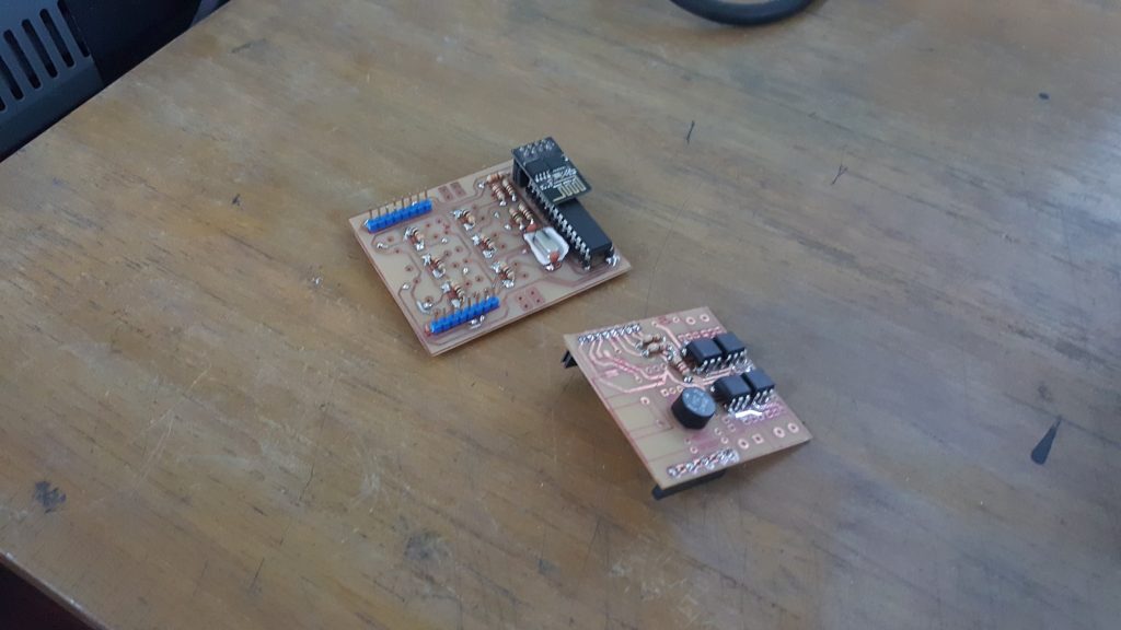
    3. Real View
  4. Final Implementation:
    1. App Interface and Physical Switch:
       
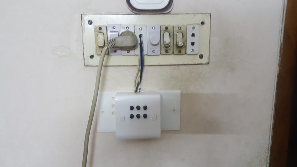
    2. Installed Device:
Prototype testing at my home.

This prototype has been running since 5th July 2018.
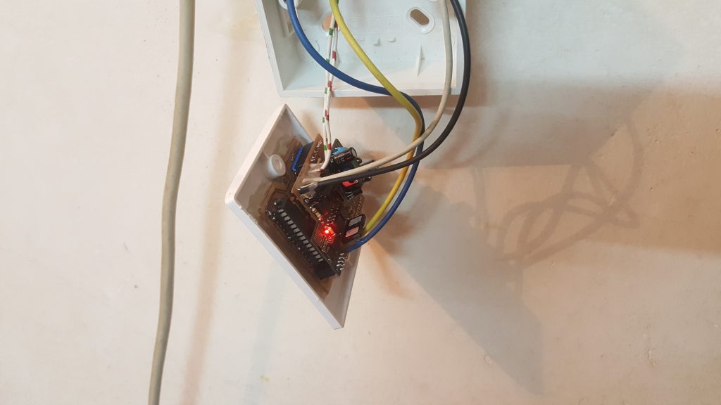
Inside the box.

[Continue reading…]

{ Comments are closed }

A small addition (foot length measuring tool) to the Pedograph Software

Pedograph is a medical device for measuring the variation of foot pressure at the various points  under the sole.
“Diabetic patients usually suffer from lack of nerve sensation, especially in the feet. Therefore, their gait on standing and during walking may deviate from that of a normal person and points of high pressure develop under the feet. However, due to neuropathy they do not feel any pain which would have been felt had the nerve functions were alright. Later, ulcers form at these high pressure points, leading to gangrene and eventual amputation of the leg. A Pedograph revealing the variation of foot pressure at various points under the sole easily delineates such high pressure regions at an early stage so that special shoe insoles can be prepared to spread the pressure away from the hot spots. This way the patient is saved from eventual amputation, from being crippled for the entire life. Again, pressure points and pattern may differ while standing and during walking, usually it is the latter which put the soles on greater burden, and a dynamic pressure measurement during walking has more importance from a clinical point of view.” (https://bibeat.com/product/dynamic-pedograph/)

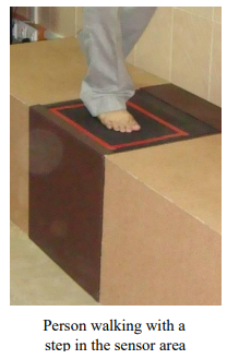
The main sensor unit (Fig) uses an optical method to create an
image of light intensities proportional to the pressure impressed at
individual points. This sensor unit provides a video image and rest of the work is done by software.
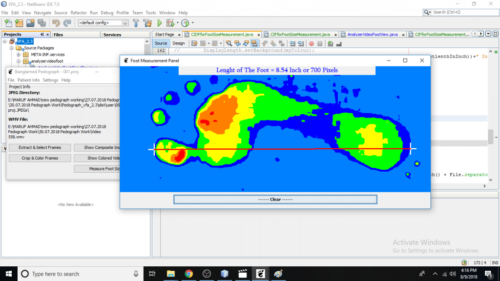
In this software, I have added a tool for measuring foot length from the composite image.

Foot length measurement tool


Below is the fundamental portion of the code.

private void footDisplayPanelMouseClicked(java.awt.event.MouseEvent evt) {                                              
// TODO add your handling code here:
int FootLength = 0;
int footLengthinInch = 0;
float ResultofFootlenthInInch =0;
MAclickCount++;
Integer x = evt.getX(), y = evt.getY();
Graphics g = footDisplayPanel.getGraphics();
Graphics2D g2 = (Graphics2D) g;
g2.setStroke(new BasicStroke(3));


int alpha = 127; // 50% transparent
Color myColour = new Color(255, 255, 255, alpha); // transparent white

g.setColor(Color.WHITE); // this is the code for pointer// the white '+' symbol
g.drawLine(x, y-15, x, y+15);
g.drawLine(x-15, y, x+15, y);

footLengthinInch = Constants.DEFAULT_PIXELS_PER_INCH;

if (MAclickCount>1){
// super.paint(g);
g.setColor(Color.red);

g2.drawLine(PreviousX, PreviousY, x, y);

FootLength = (int) Math.sqrt(((PreviousX-x)*(PreviousX-x))+((PreviousY-y)*(PreviousY-y)));
ResultofFootlenthInInch = (float)FootLength/footLengthinInch;

// footDisplayPanel.setBackground(myColour);
// DisplayLength.setBackground(myColour);
DisplayLength.setText("Lenght of The Foot = "+(String.format("%.2f", ResultofFootlenthInInch))+" Inch or "+FootLength+" Pixels");
// DisplayLength.setBackground(myColour);

}
if (MAclickCount>=2){ // for refreaching after two click.
PreviousX = 0;
PreviousY = 0;
MAclickCount =0;
x =0;
y=0;
}
PreviousX = x;
PreviousY = y;

}
Foot length measuring tool's code


[Continue reading…]

{ Comments are closed }