Introducing the Smartphone USB OTG Powered Electronic Stethoscope:
At the Biomedical Physics and Technology Department at the University of Dhaka, we have developed a groundbreaking device—a smartphone-powered electronic stethoscope. This innovative device is designed to be a small, low-cost solution that requires no battery and can be easily attached to a smartphone. The electronic stethoscope is an excellent example of leveraging modern technology to improve healthcare accessibility and efficiency.
Key Features and Components:
The electronic stethoscope system is built to deliver high-quality audio output of heart and lung sounds while being convenient and user-friendly. Here’s a breakdown of the major components and their functions:
- Smartphone Integration: Utilizes the smartphone’s USB OTG (On-The-Go) capability to power the device, eliminating the need for an external power source.
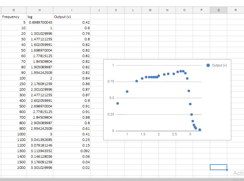
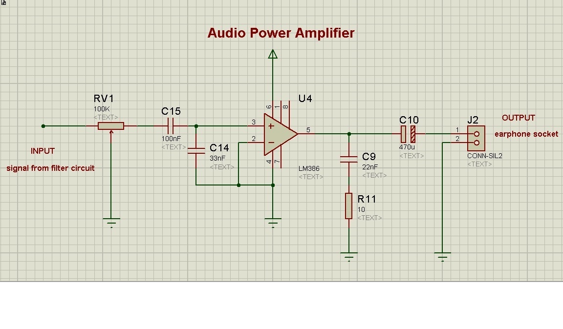
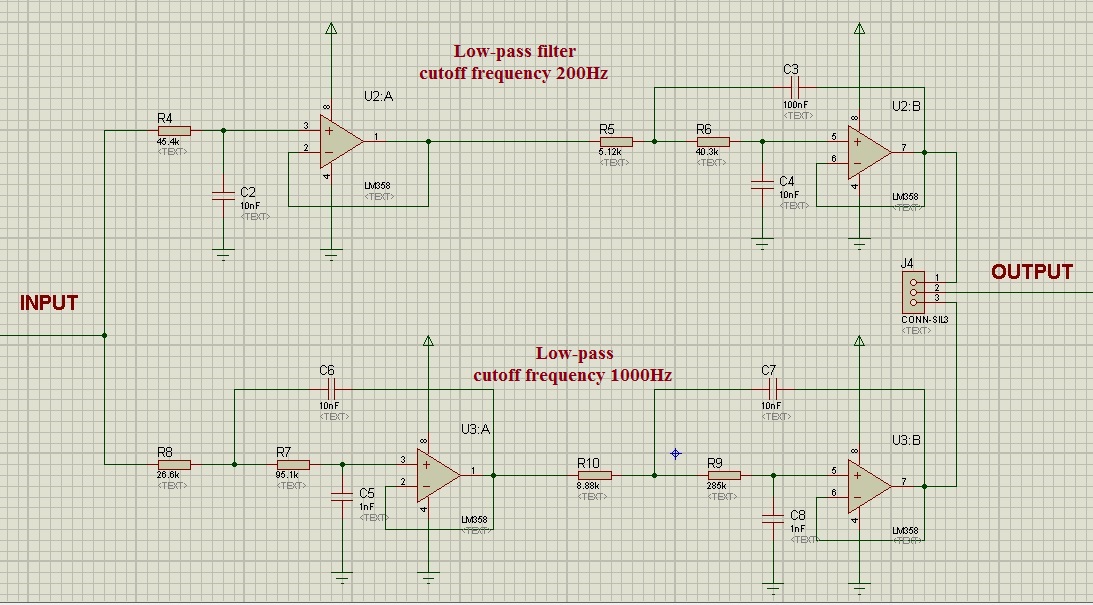
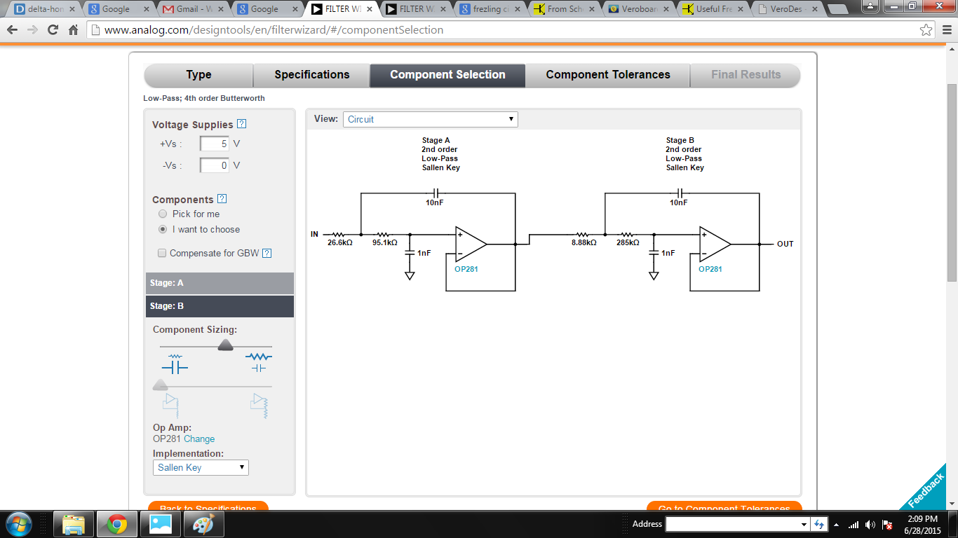
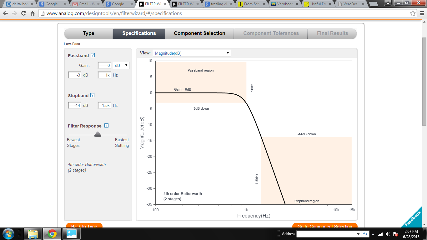
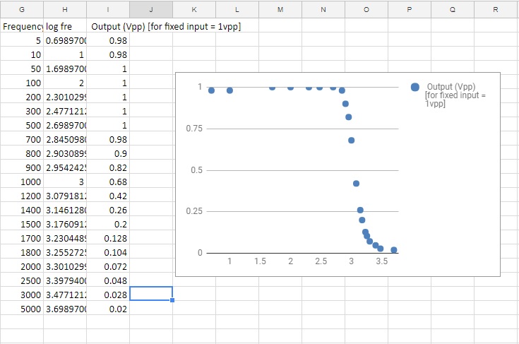
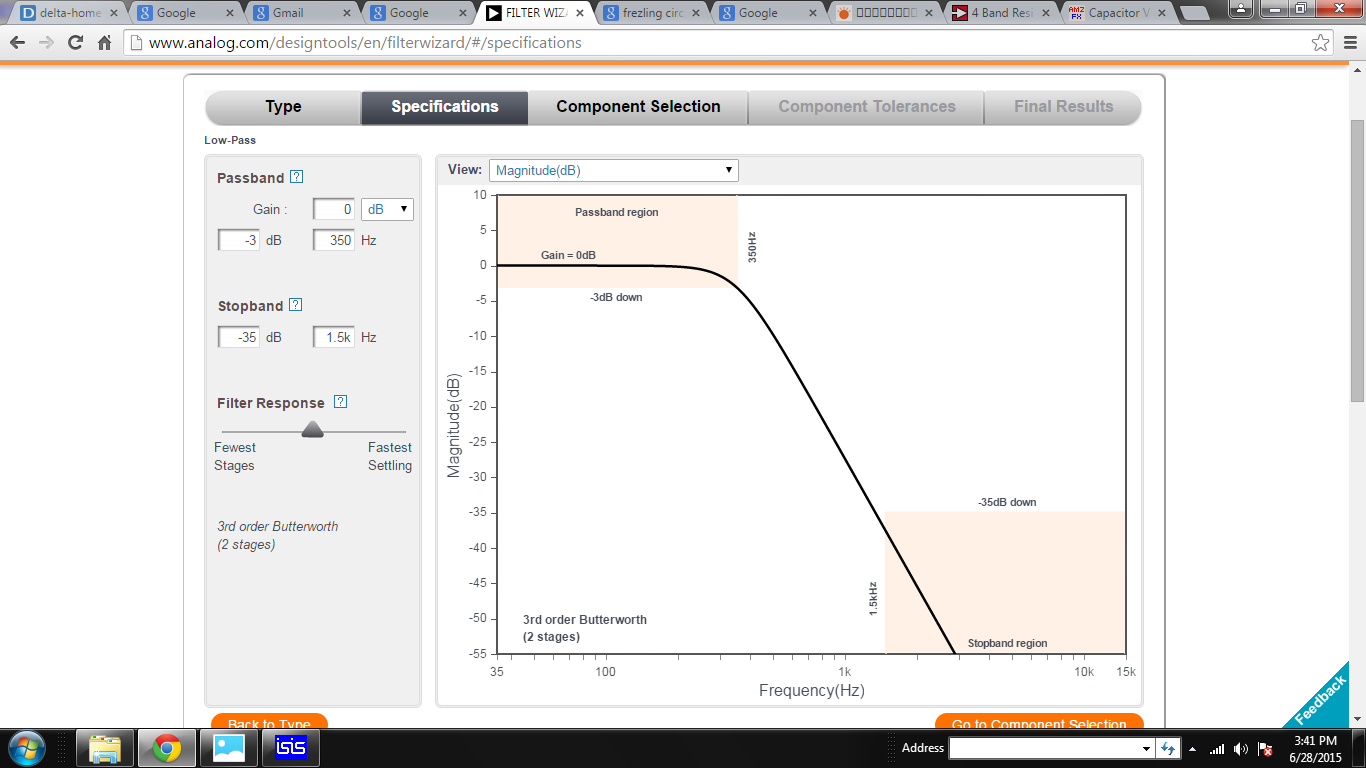
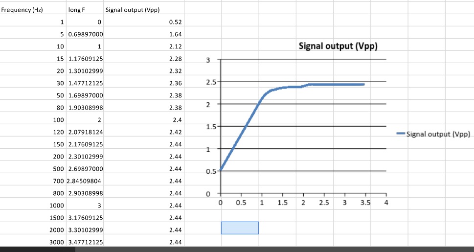
- Amplifiers and Filters: Ensures clear and precise amplification of body sounds for accurate diagnosis.
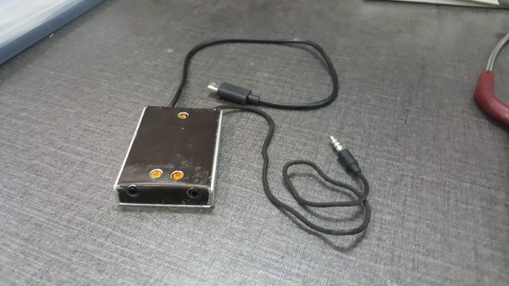
- Compact Design: The circuit is designed to be compact and lightweight, making it highly portable and easy to use.
Software and Functionality:
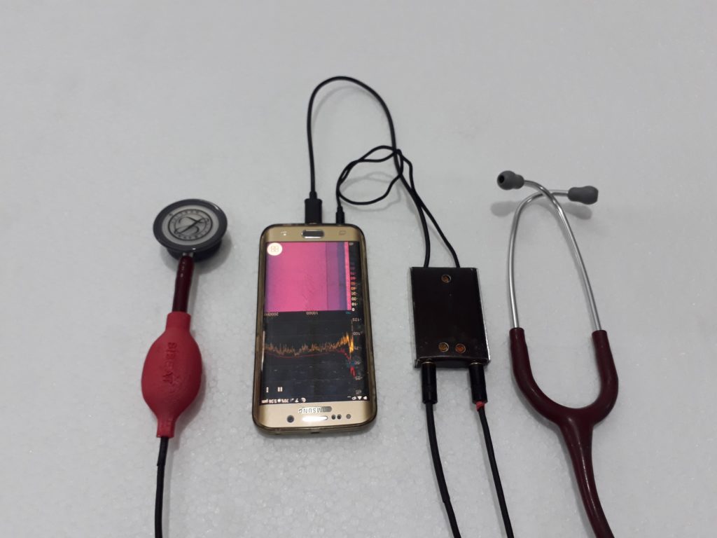
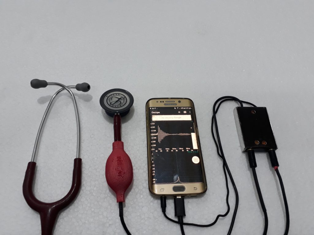
The device interfaces with a smartphone via a custom app, which allows healthcare professionals to visualize and record the stethoscope’s output. This functionality not only aids in immediate diagnosis but also provides an opportunity for remote consultations and second opinions.
Visuals and Demonstrations:
Below are some images showcasing the design and implementation of the smartphone USB OTG powered electronic stethoscope:
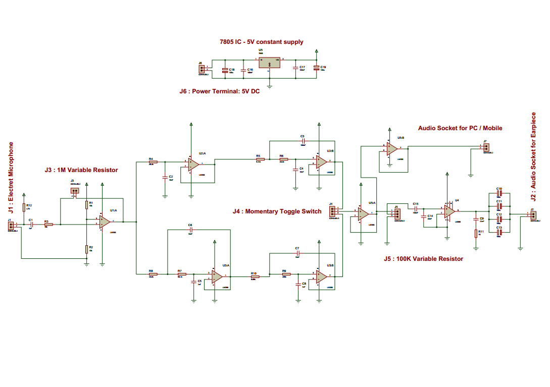
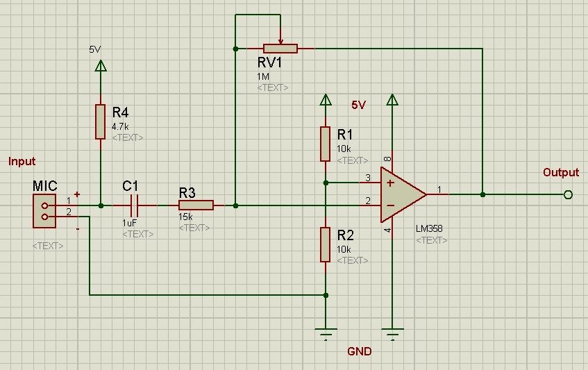
- Schematic Diagram:
- Stethoscope Schematic:

- Stethoscope Schematic:
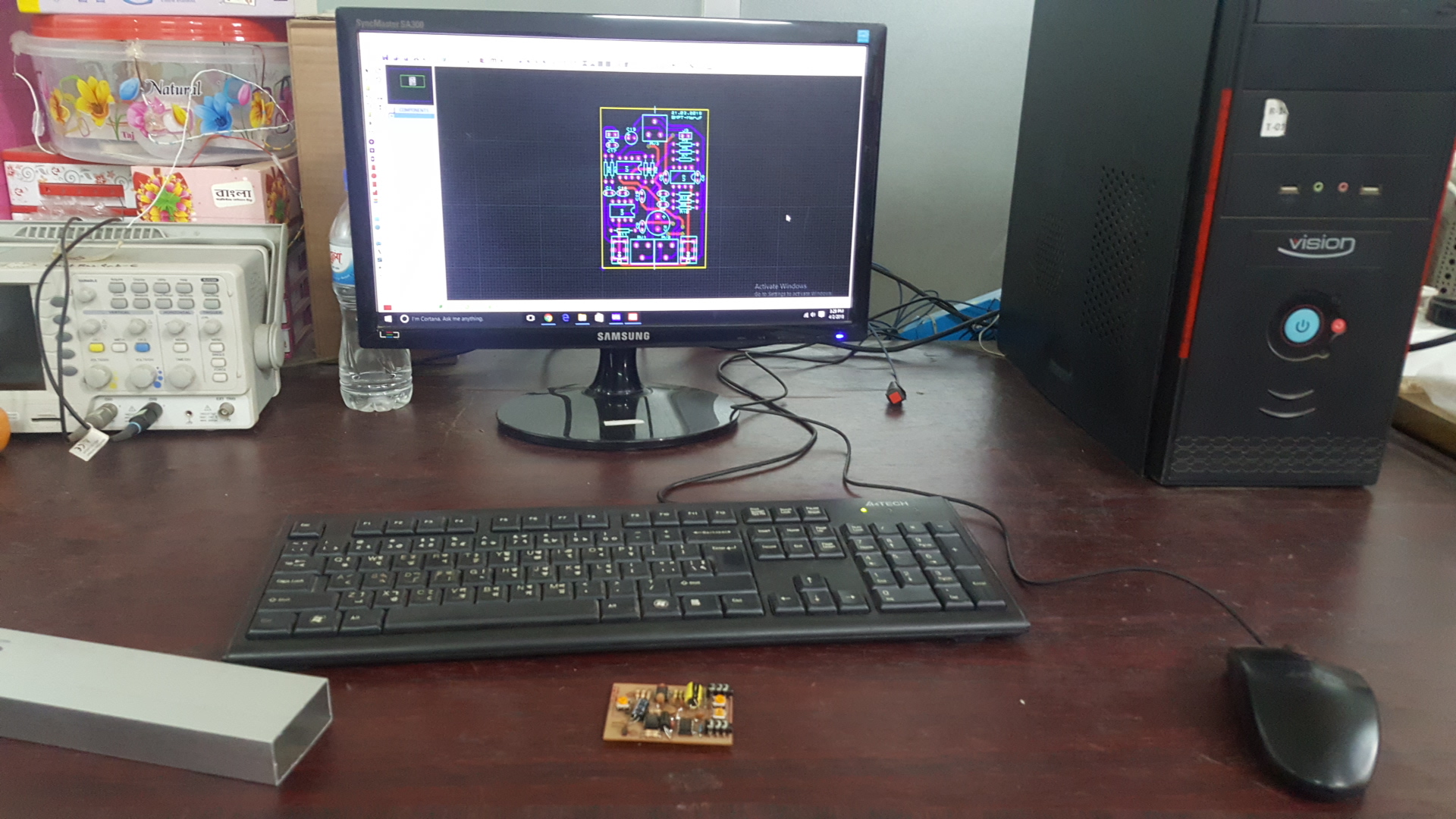
- PCB Layout:
- Stethoscope PCB Layout:

- Stethoscope PCB Layout:
- 3D PCB View:
- 3D View of Stethoscope PCB:

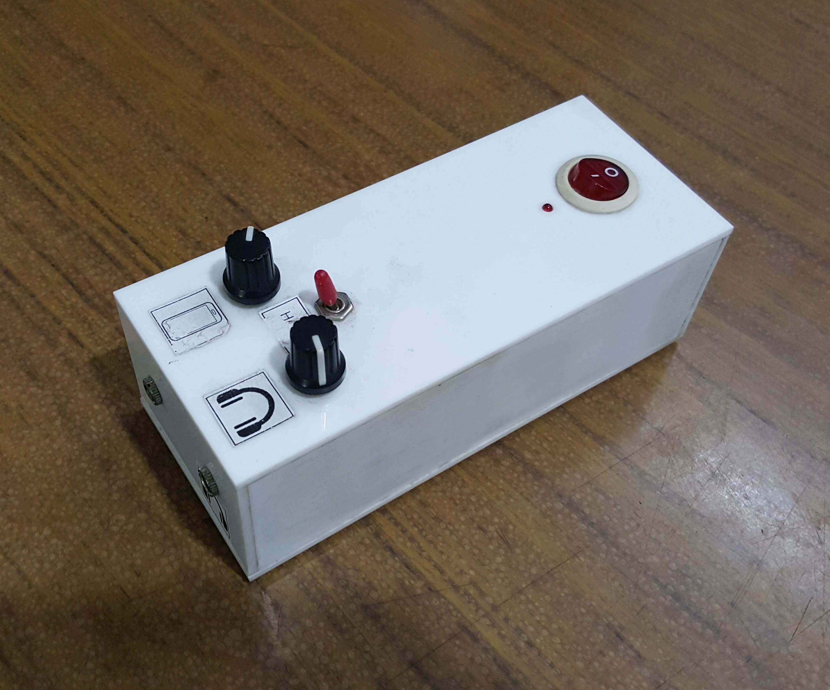
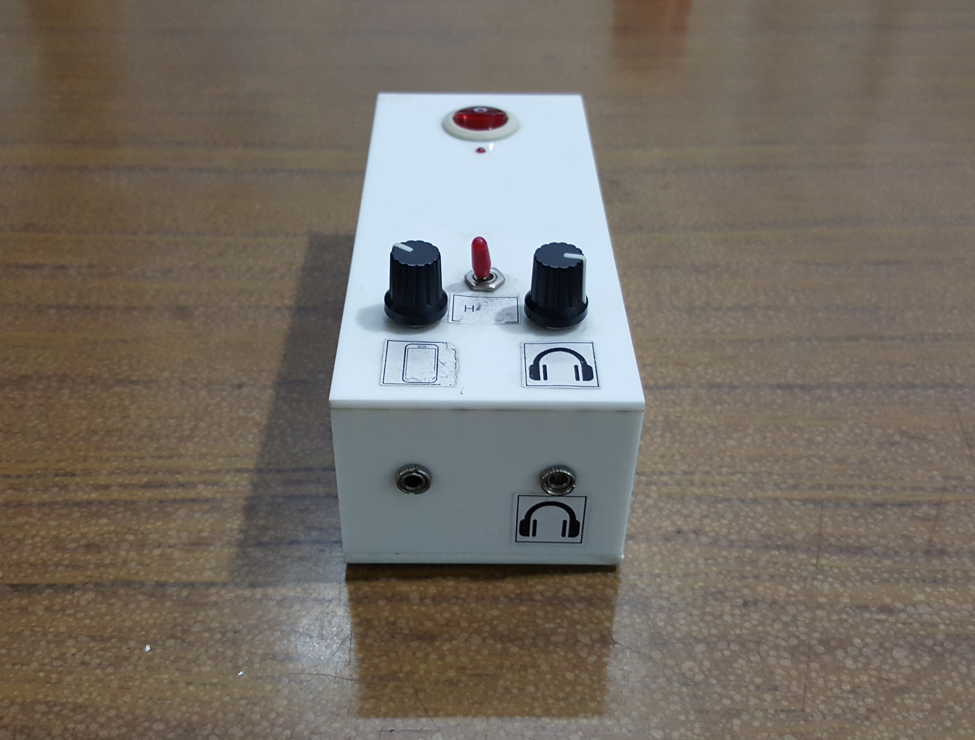
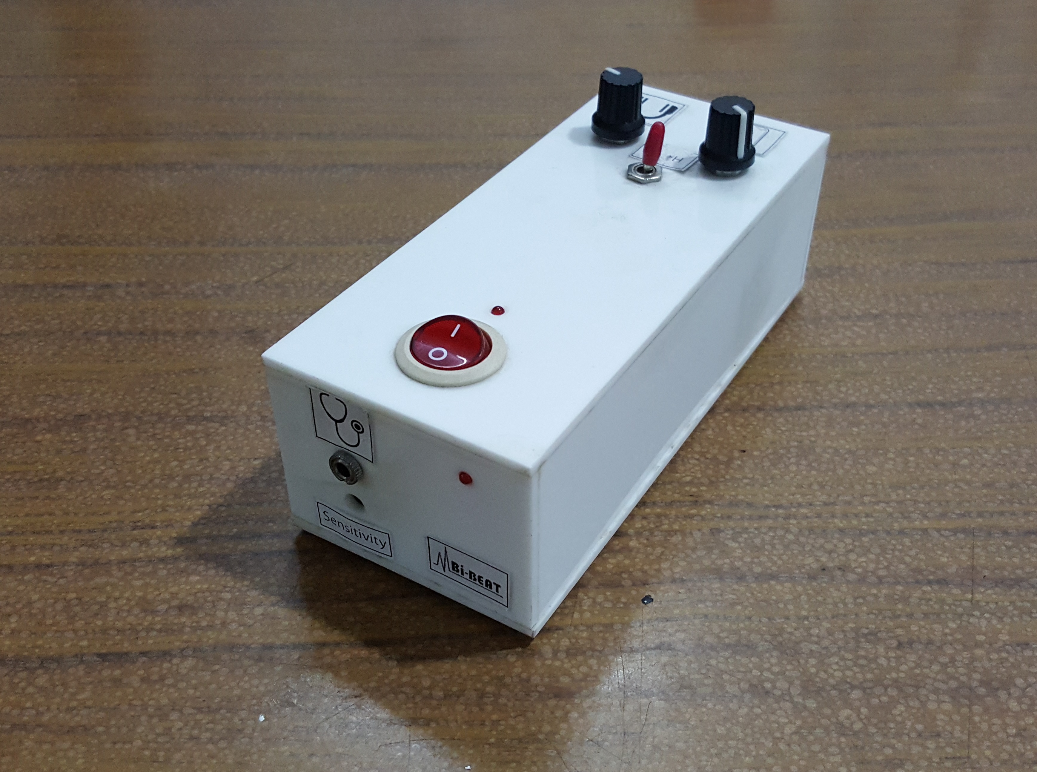
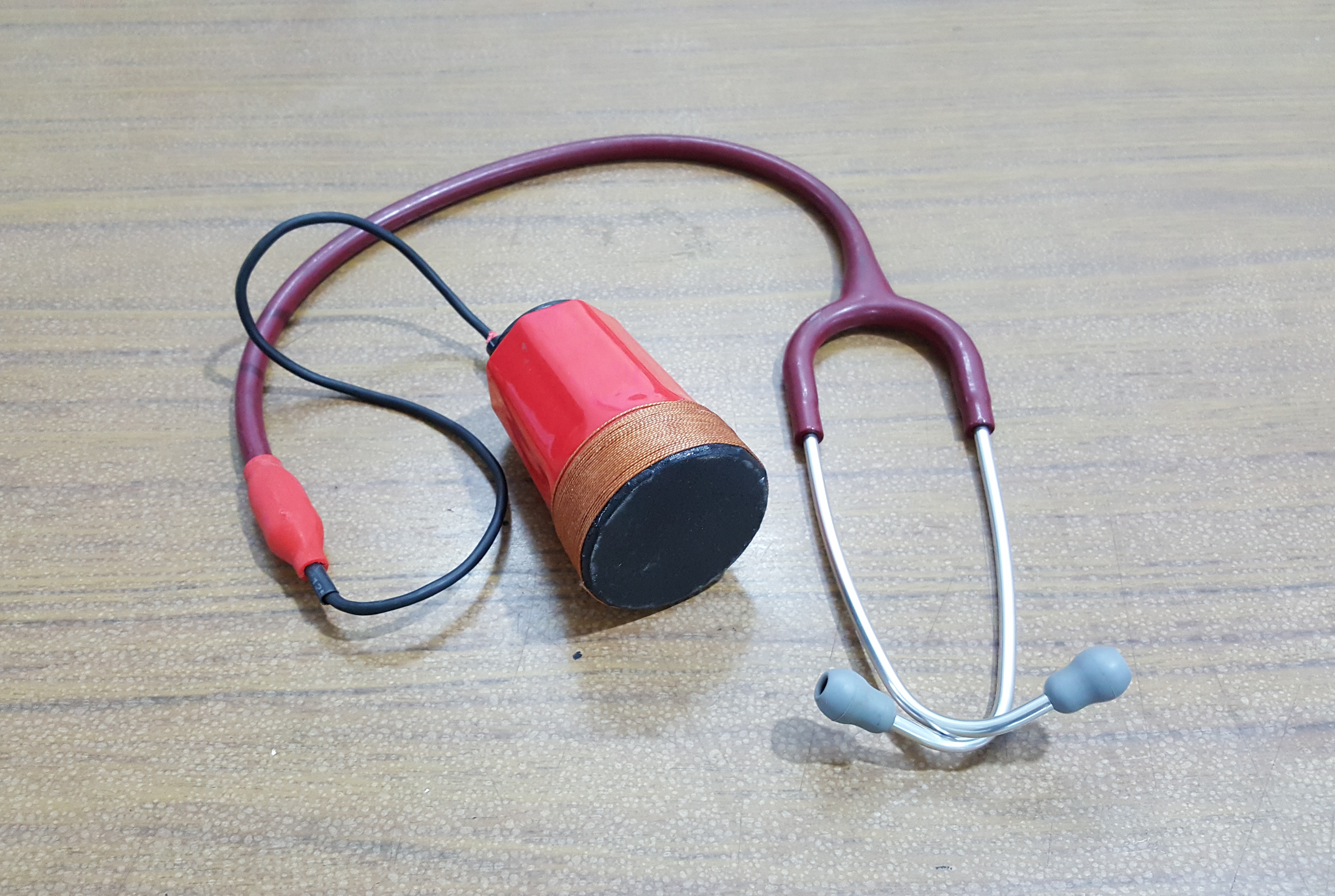
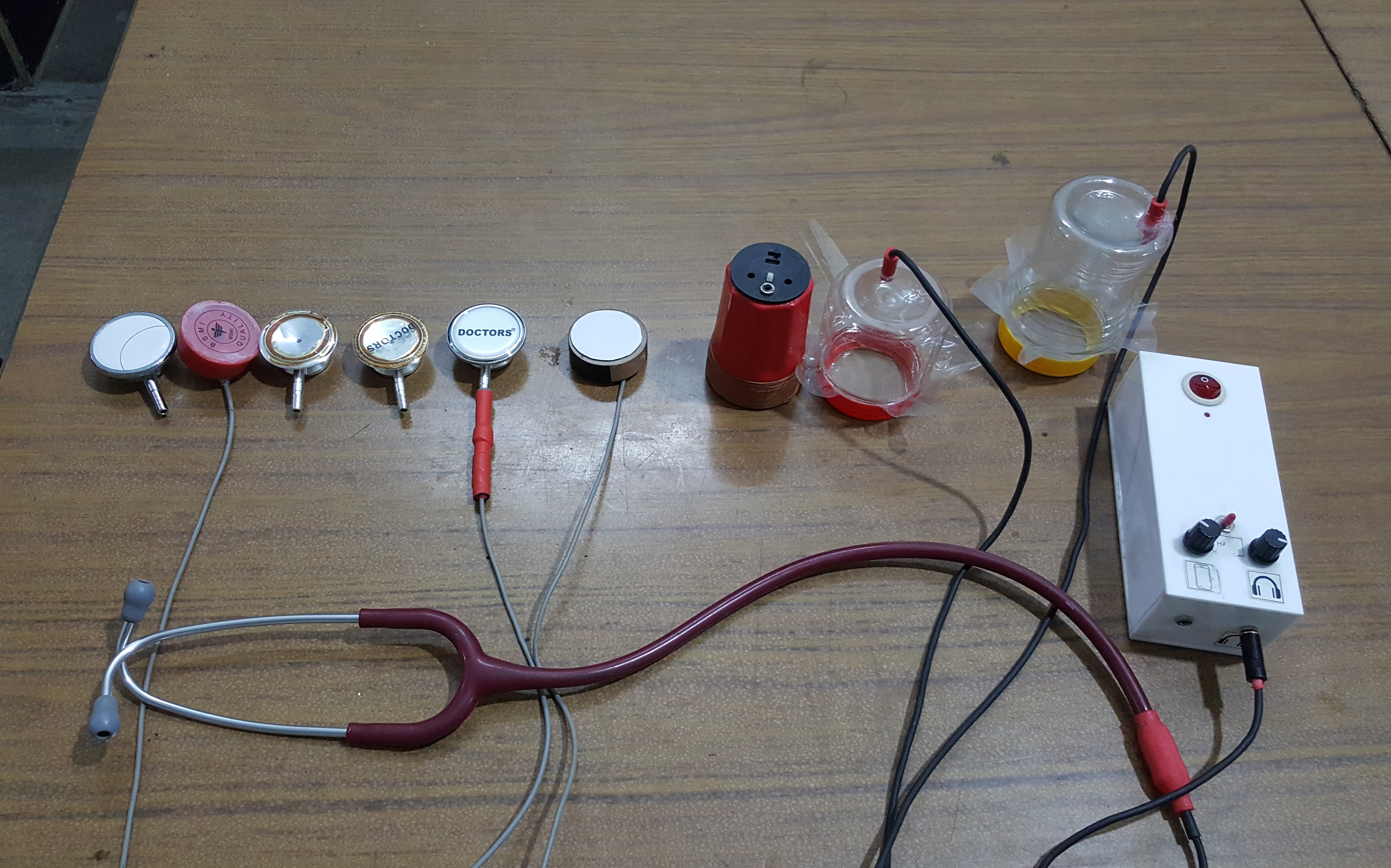
- Real View of the Stethoscope’s Amplifier
- 3D View of Stethoscope PCB:


This project highlights our commitment to developing innovative medical devices that are both affordable and effective. The smartphone USB OTG powered electronic stethoscope represents a significant advancement in medical diagnostics, making it easier for healthcare professionals to perform auscultations and monitor patient health efficiently.