I recently worked on a project where I integrated an ILI9341 TFT display with touch functionality into an STM32F103RB board. The goal was to display text and handle touch events, such as clicking buttons, while ensuring the display orientation could be changed by a button press. Here’s a detailed walkthrough of the process.
This tutorial will guide you through connecting an ILI9341 TFT display to an STM32F103RB microcontroller on a Nucleo-64 board, displaying text, and rotating the display orientation using a push button.
This device is a part of a bus service automation system. The full system consists mobile application for users, servers for data storages, and application for bus company.
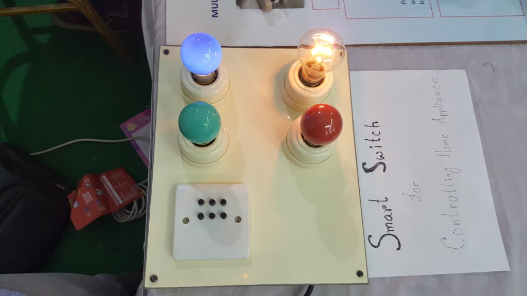
Introducing the WiFi IoT Electric Switch: A Leap Towards Smart Home Automation
In 2017, I embarked on an exciting project to develop a WiFi IoT Electric Switch aimed at transforming the way we control electrical appliances such as lights, fans, and other equipment up to 150 Watts. This innovative device enables users to manage and monitor their appliances from anywhere in the world, provided there is an internet connection.
Key Features and Components:
The WiFi IoT Electric Switch is built around the low-cost, highly efficient ESP8266 WiFi module, complemented by the Atmega8 microcontroller. Here’s a breakdown of the major components and their functions:
ESP8266 WiFi Module: This module provides the device with wireless connectivity, allowing it to interface with the internet seamlessly.
Atmega8 Microcontroller: Serves as the brain of the switch, managing inputs, outputs, and processing.
Triacs and Optocouplers: These components are crucial for switching and controlling the electrical loads safely.
5V 1A SMPS Power Supply: Ensures that the entire system receives a stable power supply.
For controlling fan speeds and light dimming, the device employs the zero-crossing detection technique, which improves efficiency and performance.
Software and Protocols:
The firmware for the ESP8266 module was developed using the ESP8266-arduino library, which is available at ESP8266-Arduino Library. This library provides a robust foundation for programming the module in a familiar Arduino environment.
Additionally, for handling communication via the MQTT protocol, the device utilizes the ThingsBoard.io IoT platform. This platform offers comprehensive support for IoT device management and data visualization, ensuring a seamless user experience.
Visuals and Demonstrations:
Below are some images showcasing the design and implementation of the WiFi IoT Electric Switch:
Schematic Diagrams:
AVR Part Schematic:
Schematic Diagram pf IoT-WiFi-Switch’s Microcontroller Part
Switching Part Schematic
Schematic Diagram of IoT-Wifi-Switch Switching Part
3D PCB Views:
PCB AVR Part:
PCB Switch Part:
PCB Layouts:
3D View of Microcontroller Part PCB Layout:
3D View of Switching Part PCB Layout:
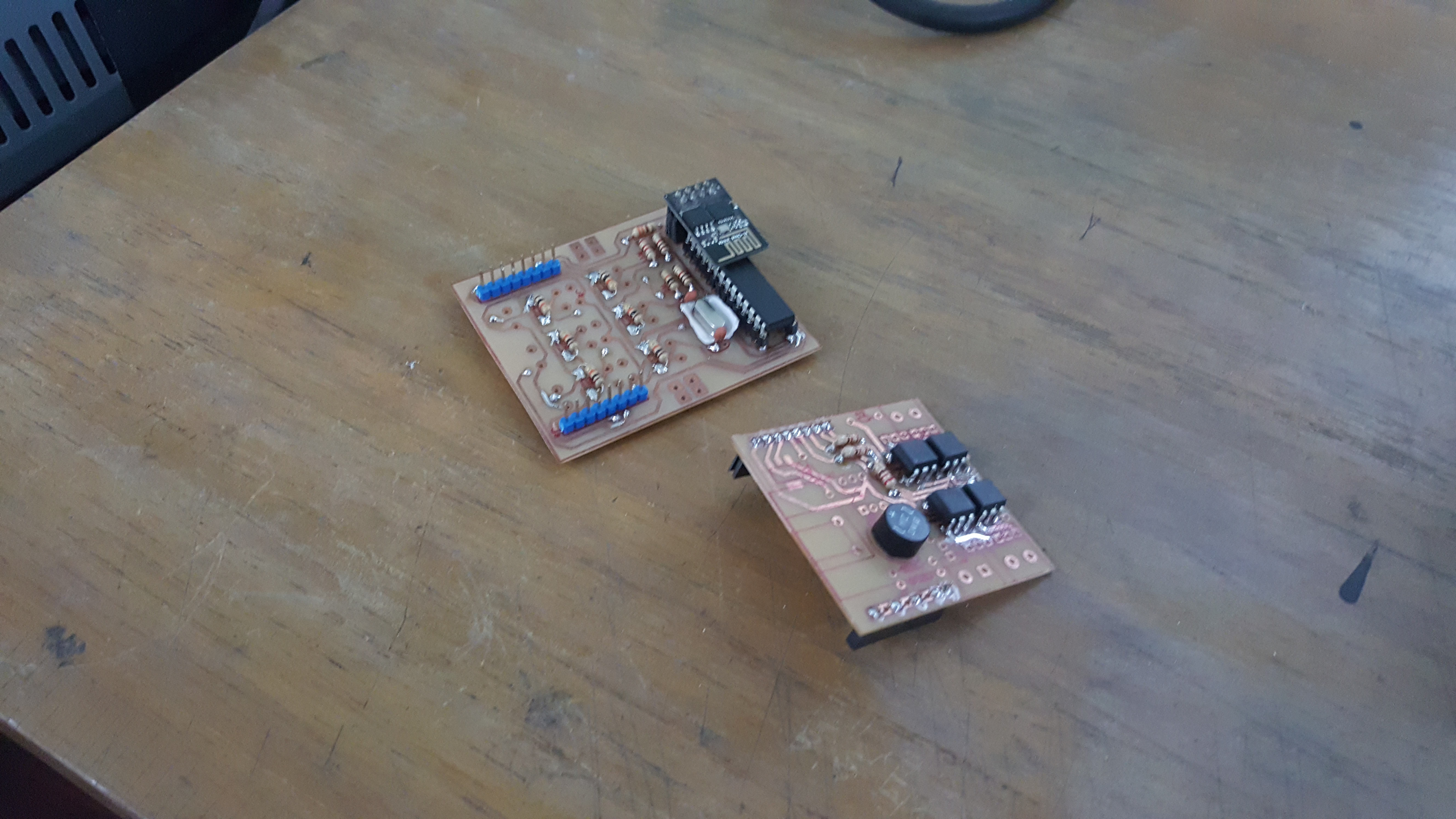
Real View
Final Implementation:
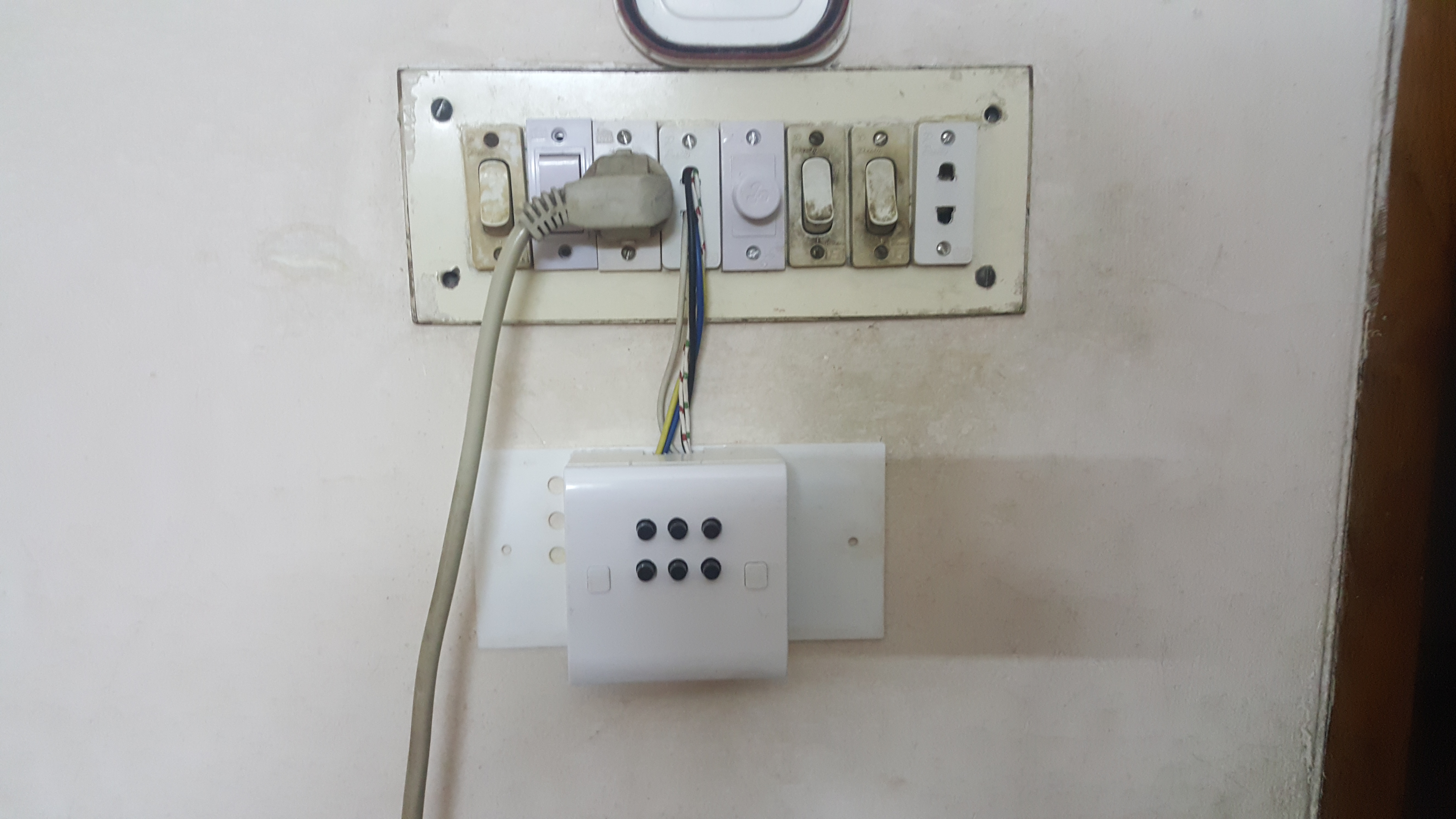
App Interface and Physical Switch:
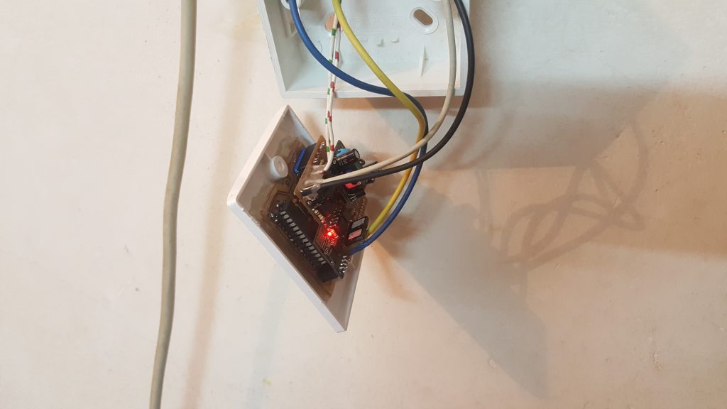
Installed Device:
Prototype testing at my home.
This prototype has been running since 5th July 2018.
Pedograph is a medical device for measuring the variation of foot pressure at the various points under the sole.
“Diabetic patients usually suffer from lack of nerve sensation, especially in the feet. Therefore, their gait on standing and during walking may deviate from that of a normal person and points of high pressure develop under the feet. However, due to neuropathy they do not feel any pain which would have been felt had the nerve functions were alright. Later, ulcers form at these high pressure points, leading to gangrene and eventual amputation of the leg. A Pedograph revealing the variation of foot pressure at various points under the sole easily delineates such high pressure regions at an early stage so that special shoe insoles can be prepared to spread the pressure away from the hot spots. This way the patient is saved from eventual amputation, from being crippled for the entire life. Again, pressure points and pattern may differ while standing and during walking, usually it is the latter which put the soles on greater burden, and a dynamic pressure measurement during walking has more importance from a clinical point of view.” (https://bibeat.com/product/dynamic-pedograph/)
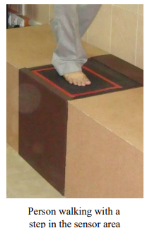
The main sensor unit (Fig) uses an optical method to create an
image of light intensities proportional to the pressure impressed at
individual points. This sensor unit provides a video image and rest of the work is done by software.
In this software, I have added a tool for measuring foot length from the composite image.
Foot length measurement tool
Below is the fundamental portion of the code.
private void footDisplayPanelMouseClicked(java.awt.event.MouseEvent evt) { // TODO add your handling code here: int FootLength = 0; int footLengthinInch = 0; float ResultofFootlenthInInch =0; MAclickCount++; Integer x = evt.getX(), y = evt.getY(); Graphics g = footDisplayPanel.getGraphics(); Graphics2D g2 = (Graphics2D) g; g2.setStroke(new BasicStroke(3));
int alpha = 127; // 50% transparent Color myColour = new Color(255, 255, 255, alpha); // transparent white
g.setColor(Color.WHITE); // this is the code for pointer// the white '+' symbol g.drawLine(x, y-15, x, y+15); g.drawLine(x-15, y, x+15, y);
// footDisplayPanel.setBackground(myColour); // DisplayLength.setBackground(myColour); DisplayLength.setText("Lenght of The Foot = "+(String.format("%.2f", ResultofFootlenthInInch))+" Inch or "+FootLength+" Pixels"); // DisplayLength.setBackground(myColour);
} if (MAclickCount>=2){ // for refreaching after two click. PreviousX = 0; PreviousY = 0; MAclickCount =0; x =0; y=0; } PreviousX = x; PreviousY = y;
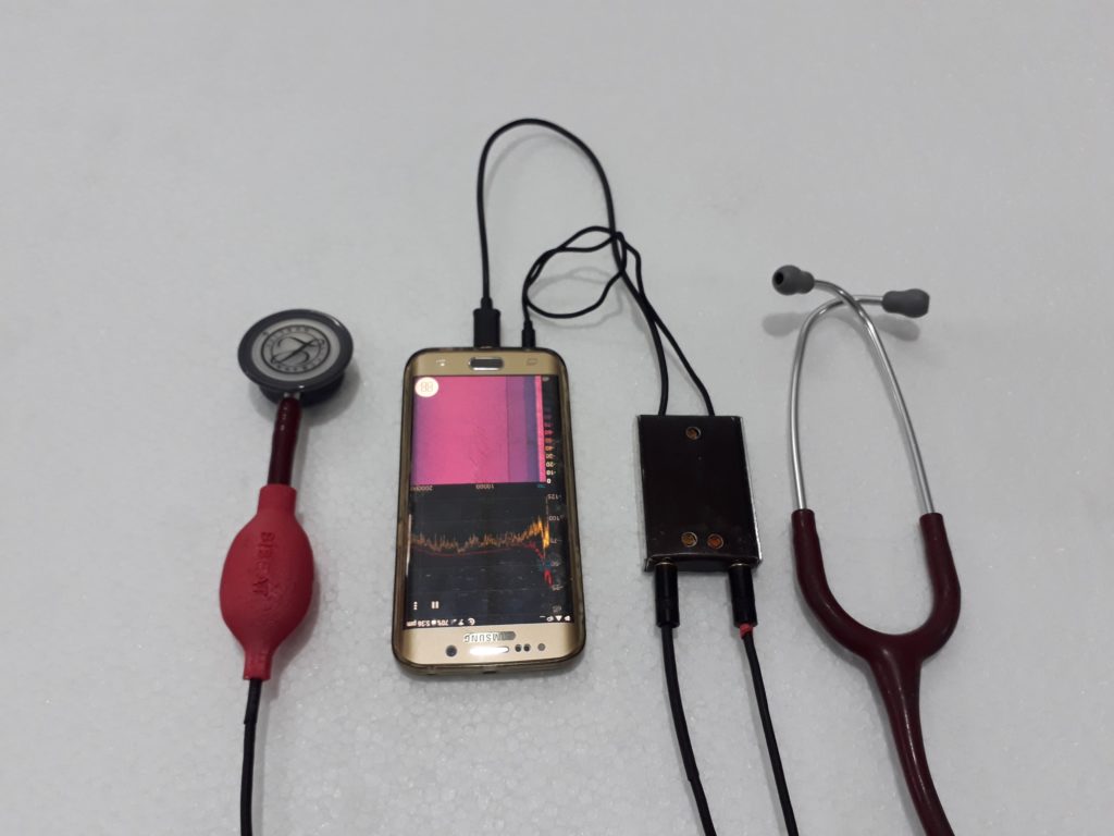
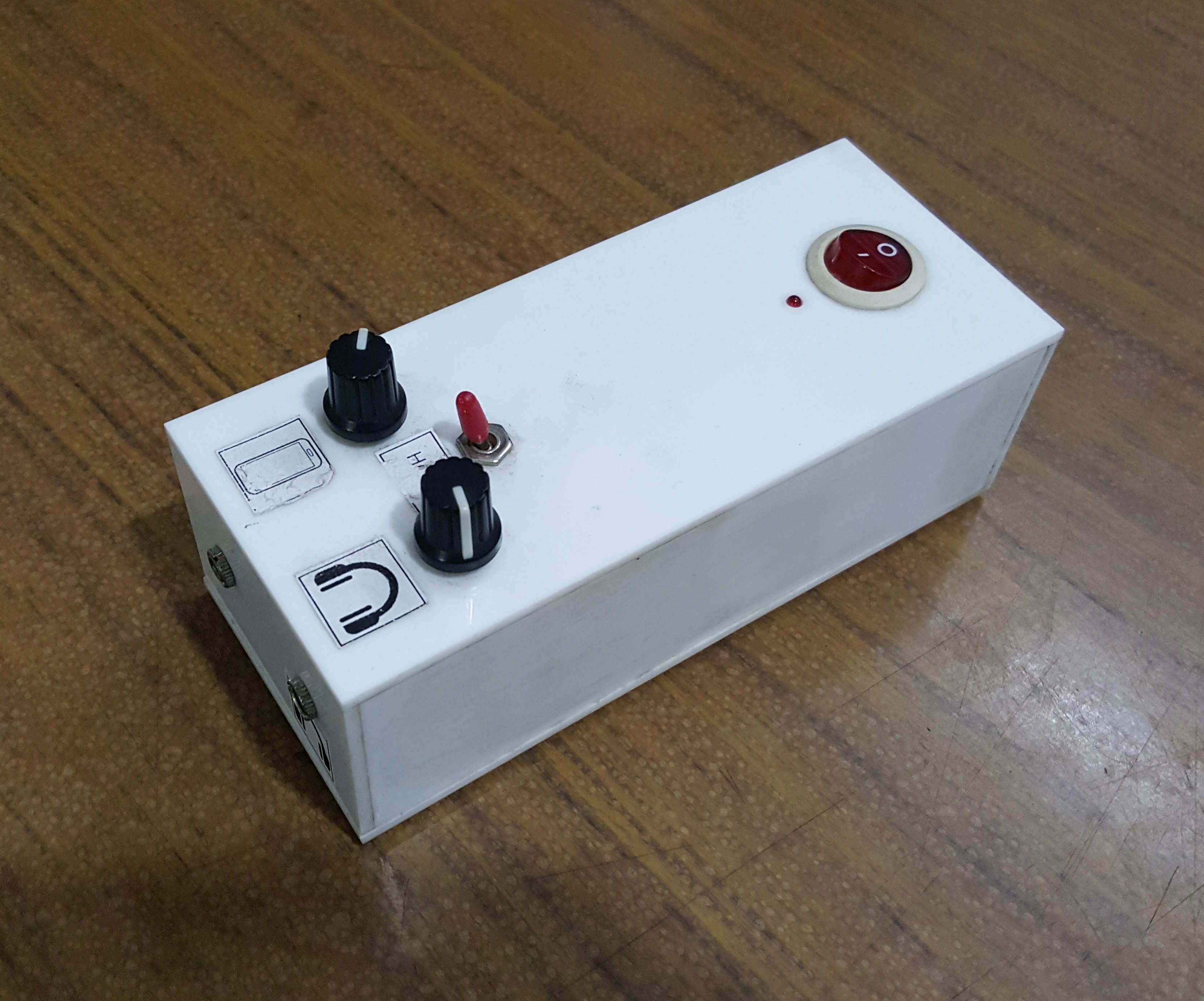
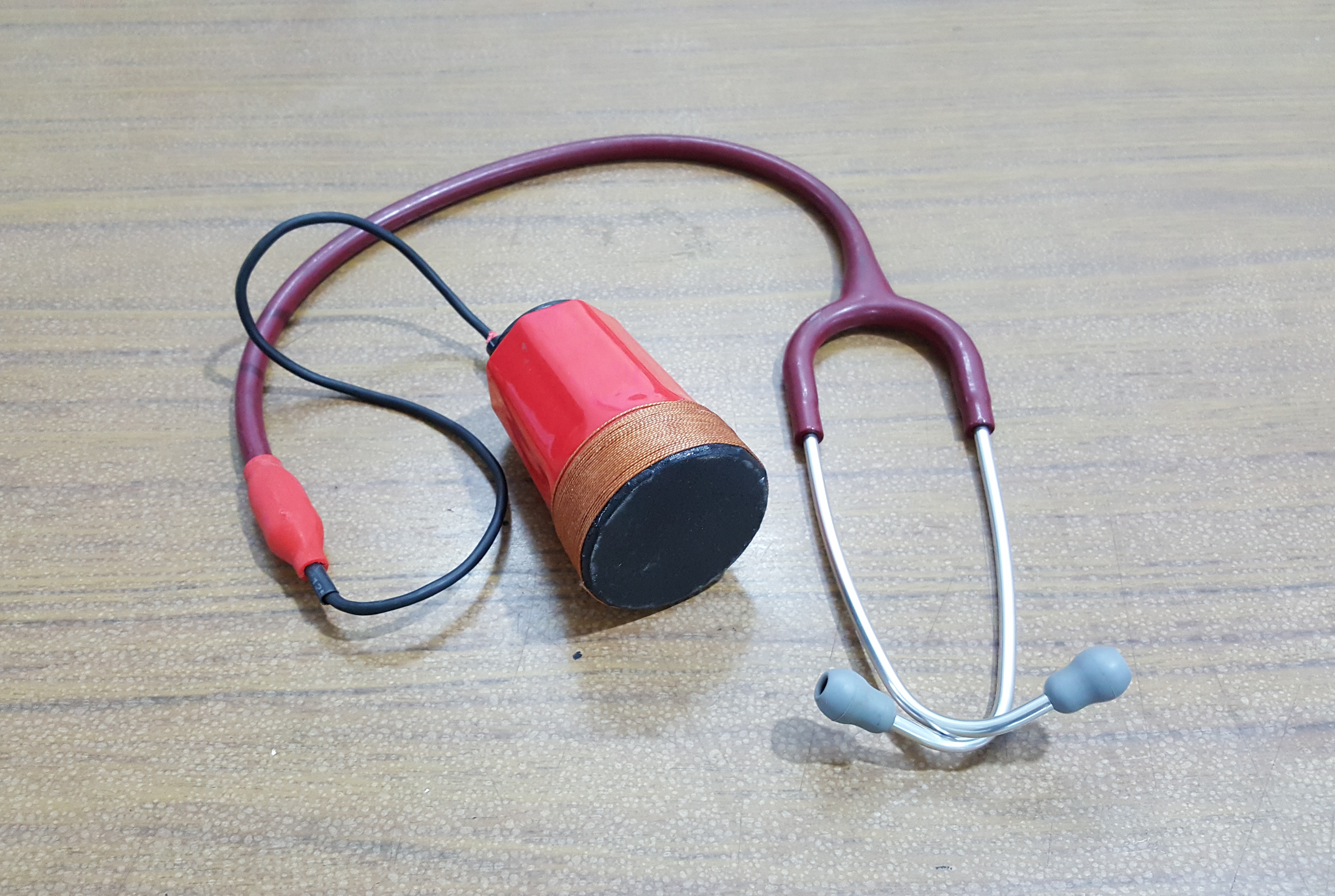
Introducing the Smartphone USB OTG Powered Electronic Stethoscope:
At the Biomedical Physics and Technology Department at the University of Dhaka, we have developed a groundbreaking device—a smartphone-powered electronic stethoscope. This innovative device is designed to be a small, low-cost solution that requires no battery and can be easily attached to a smartphone. The electronic stethoscope is an excellent example of leveraging modern technology to improve healthcare accessibility and efficiency.
Smartphone powered Electronic Stethoscope System
Key Features and Components:
The electronic stethoscope system is built to deliver high-quality audio output of heart and lung sounds while being convenient and user-friendly. Here’s a breakdown of the major components and their functions:
Smartphone Integration: Utilizes the smartphone’s USB OTG (On-The-Go) capability to power the device, eliminating the need for an external power source.
Amplifiers and Filters: Ensures clear and precise amplification of body sounds for accurate diagnosis.
Compact Design: The circuit is designed to be compact and lightweight, making it highly portable and easy to use.
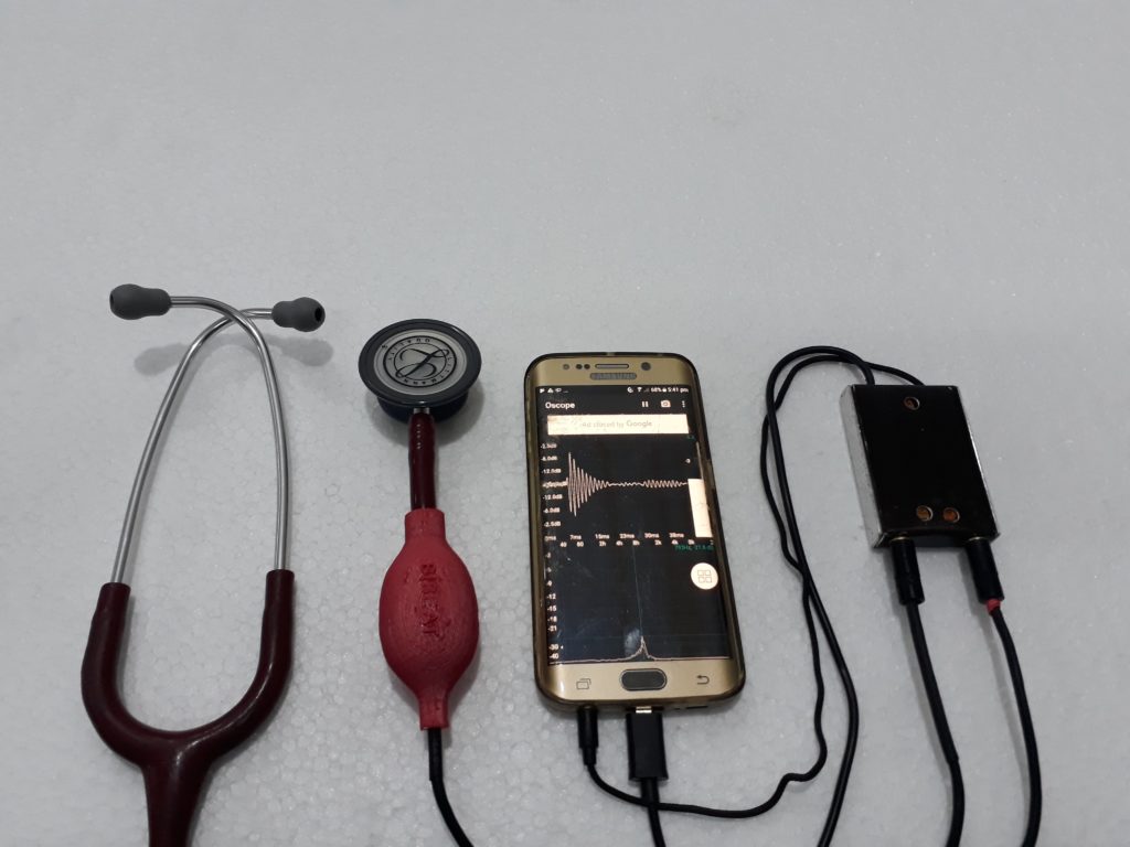
Software and Functionality:
The device interfaces with a smartphone via a custom app, which allows healthcare professionals to visualize and record the stethoscope’s output. This functionality not only aids in immediate diagnosis but also provides an opportunity for remote consultations and second opinions.
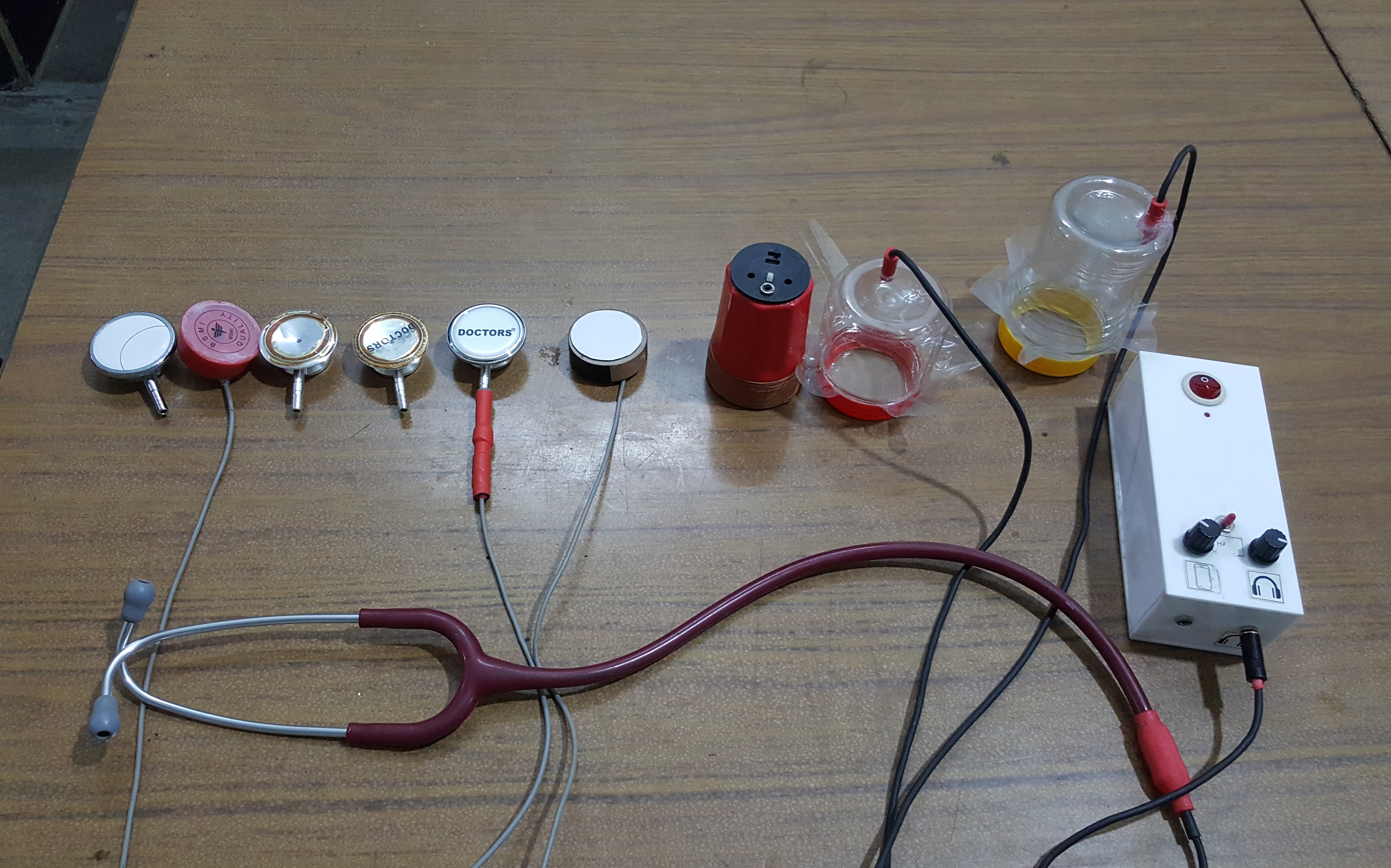
Visuals and Demonstrations:
Below are some images showcasing the design and implementation of the smartphone USB OTG powered electronic stethoscope:
Schematic Diagram:
Stethoscope Schematic:
PCB Layout:
Stethoscope PCB Layout:
3D PCB View:
3D View of Stethoscope PCB:
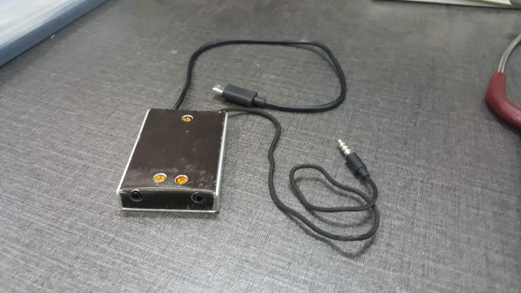
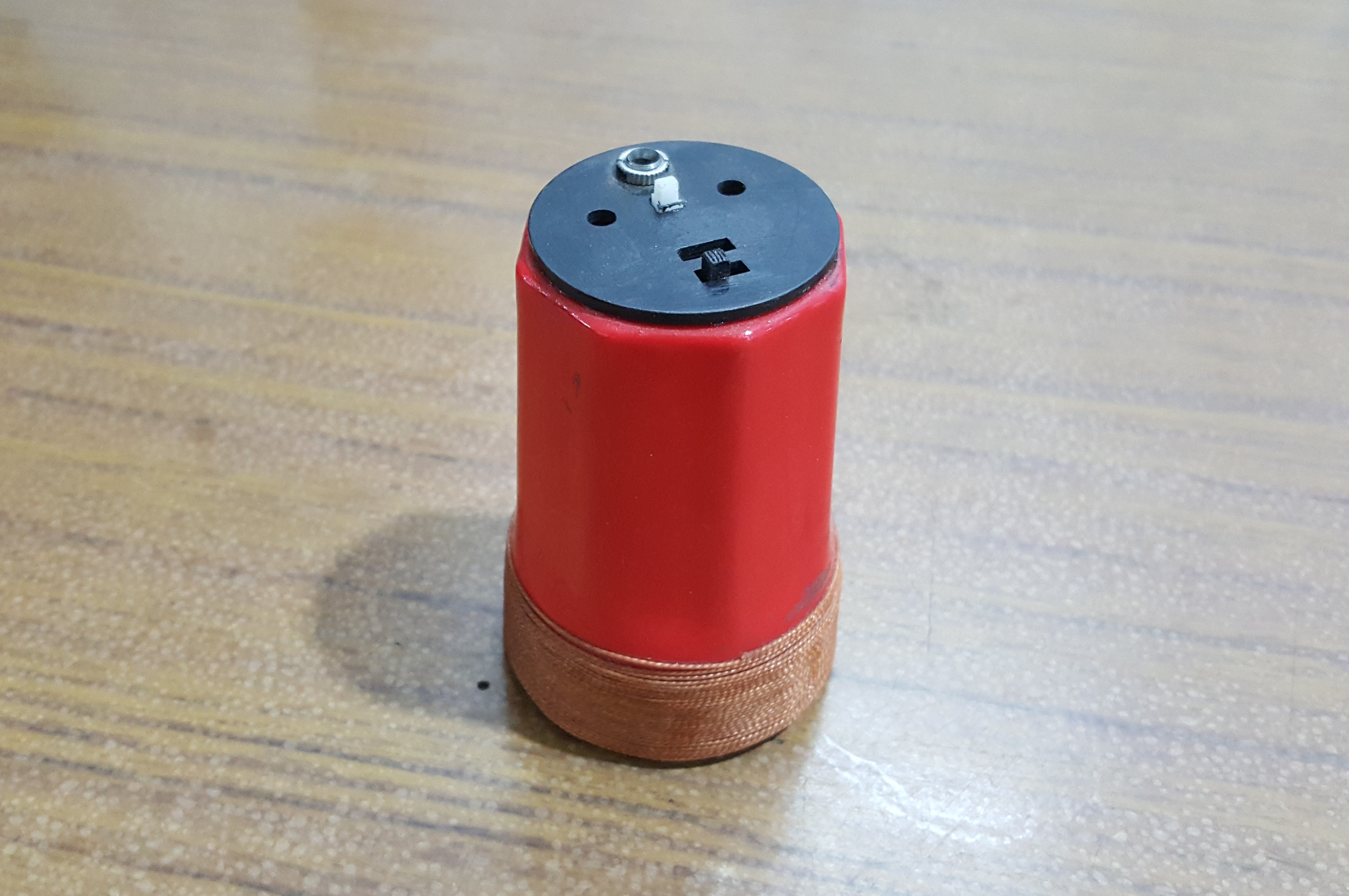
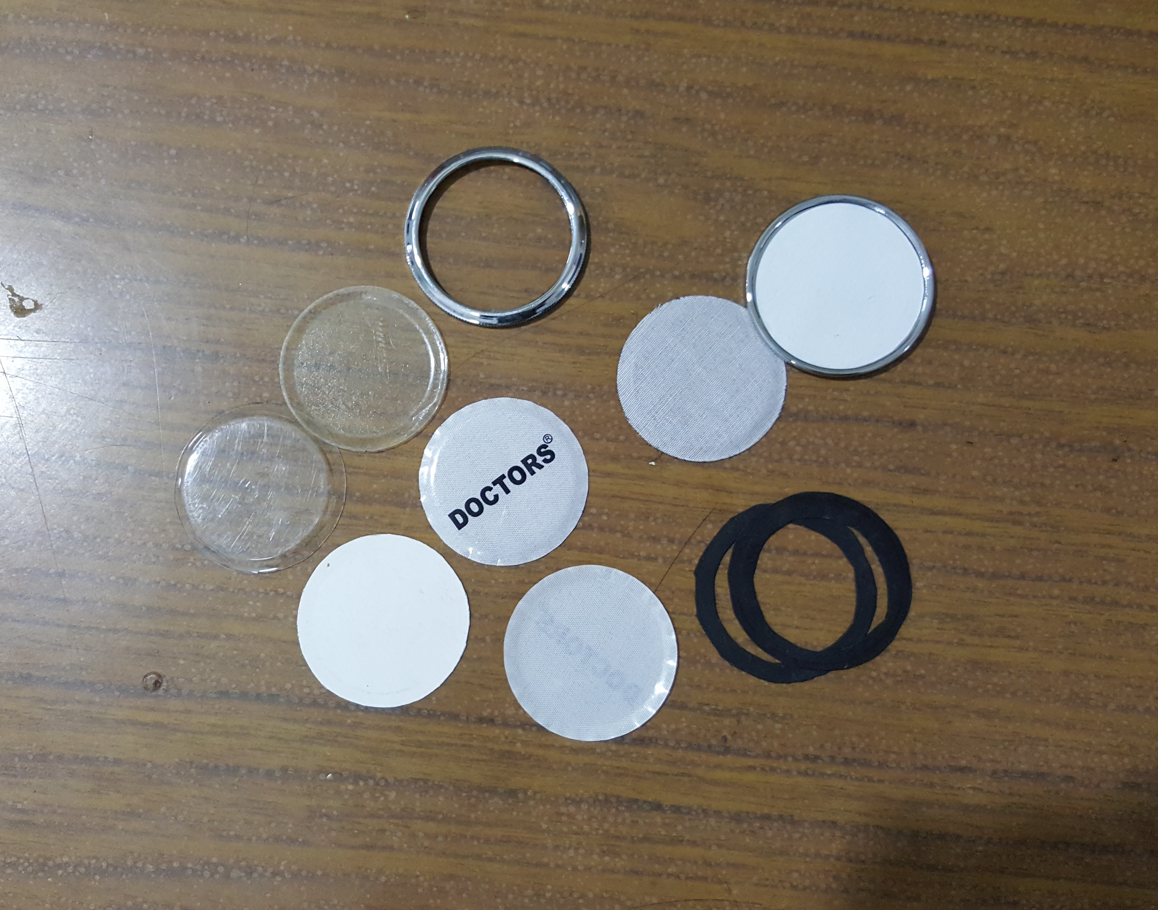
Real View of the Stethoscope’s Amplifier
OTG powered electronic stethoscope amplifierInternal Circuit of the Amplifier
This project highlights our commitment to developing innovative medical devices that are both affordable and effective. The smartphone USB OTG powered electronic stethoscope represents a significant advancement in medical diagnostics, making it easier for healthcare professionals to perform auscultations and monitor patient health efficiently.
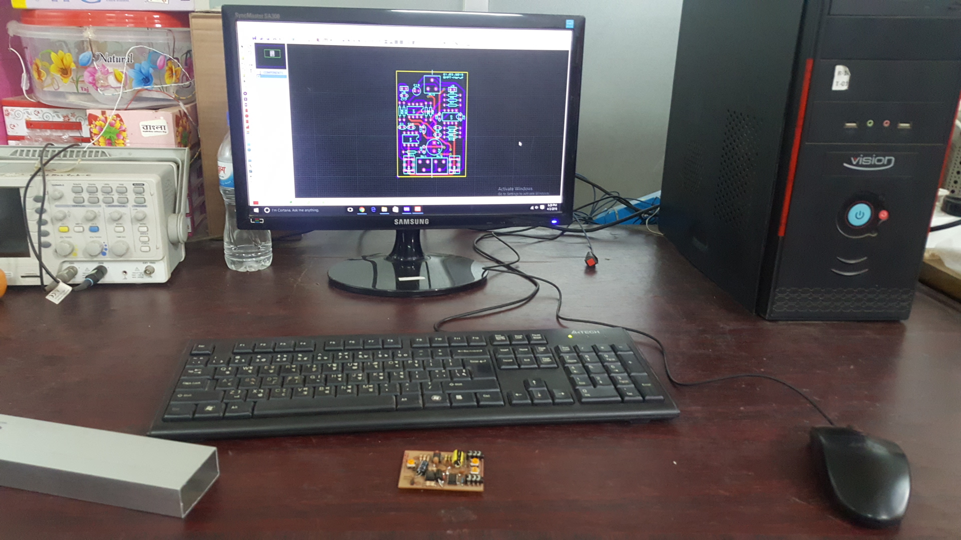
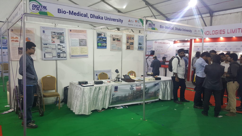
Some pictures of the Smart WiFi Switch demo board that has been displayed at BMPT stall in the Digital World 2017 – an exposition organized to showcase the progress of Bangladesh’s IT industry. The event, held at the Bangabandhu International Conference Centre in Dhaka from 6th December to 9th December.
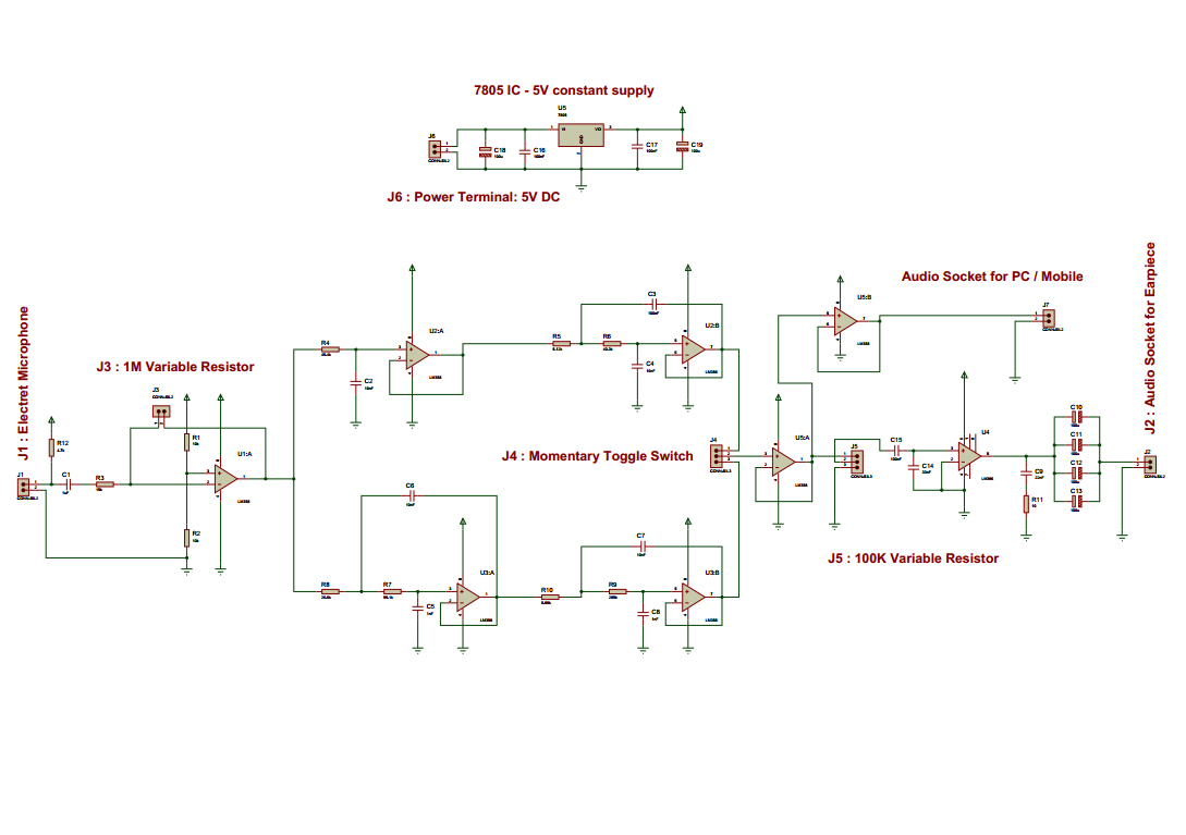
Complete Circuit diagram of our electronic stethoscope is shown below.
Full Circuit Diagram
I discussed every stage of the circuit in my previous posts. Here it just shows the integration of all of the parts and a constant 5V DC supply circuit (top in the picture) is added.
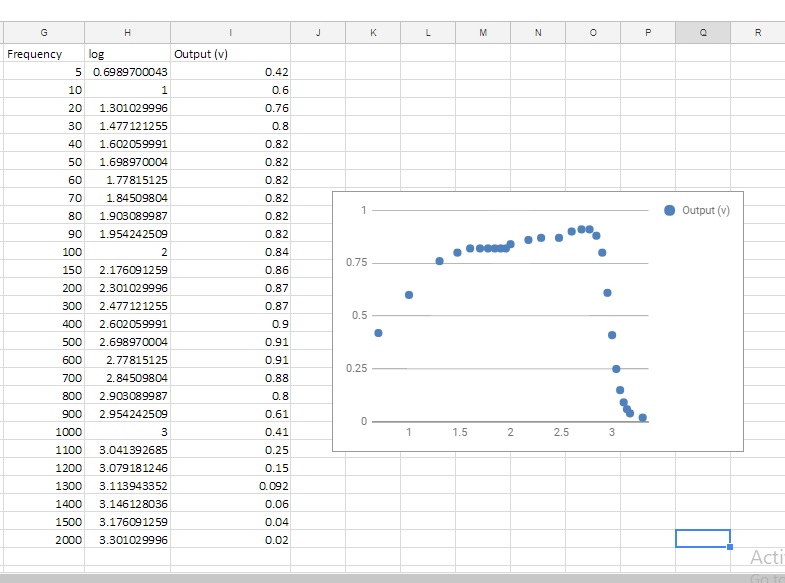
The overall performance of the circuit:
Frequency Response:
Frequency Response of the Overall Circuit
Completed circuit:
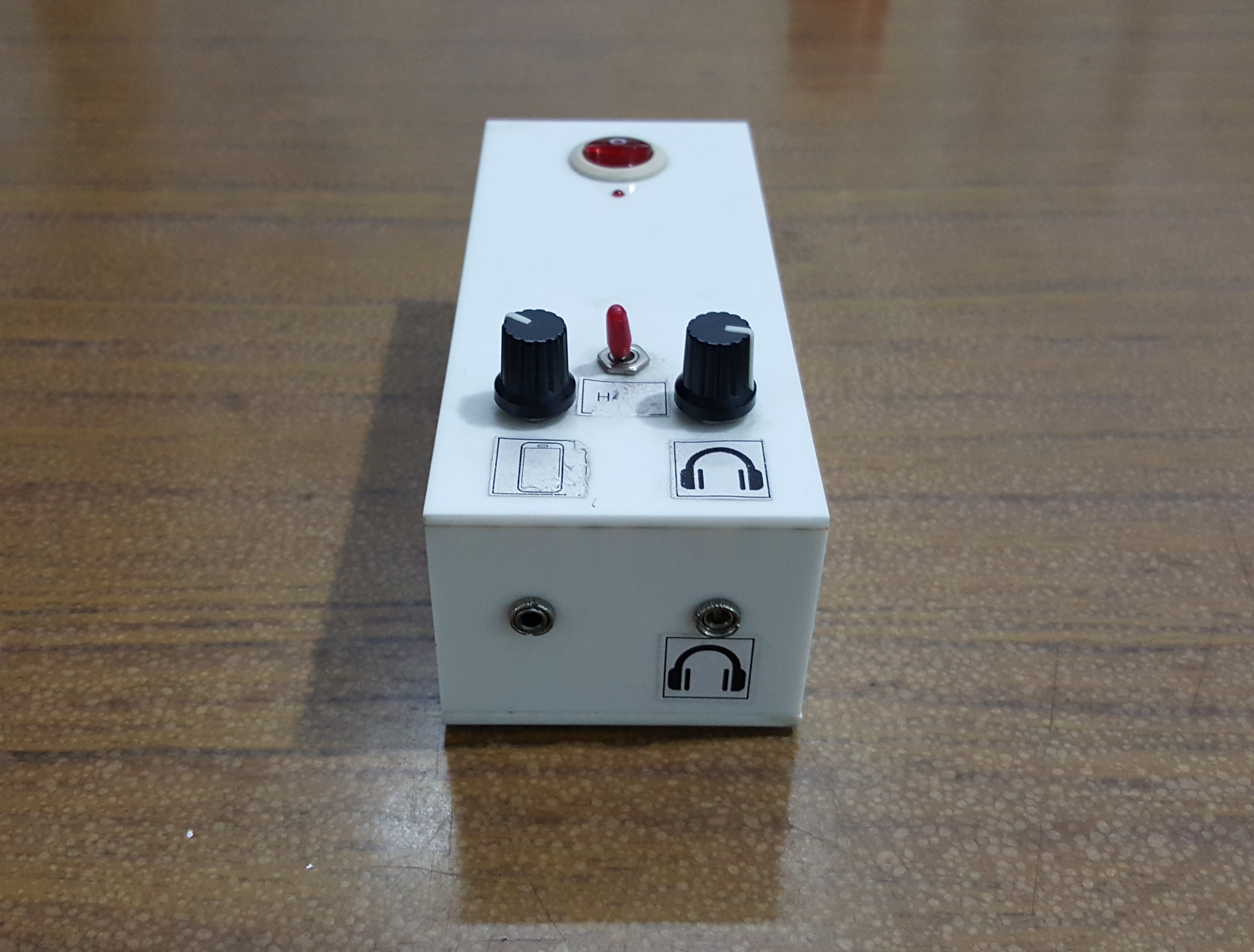
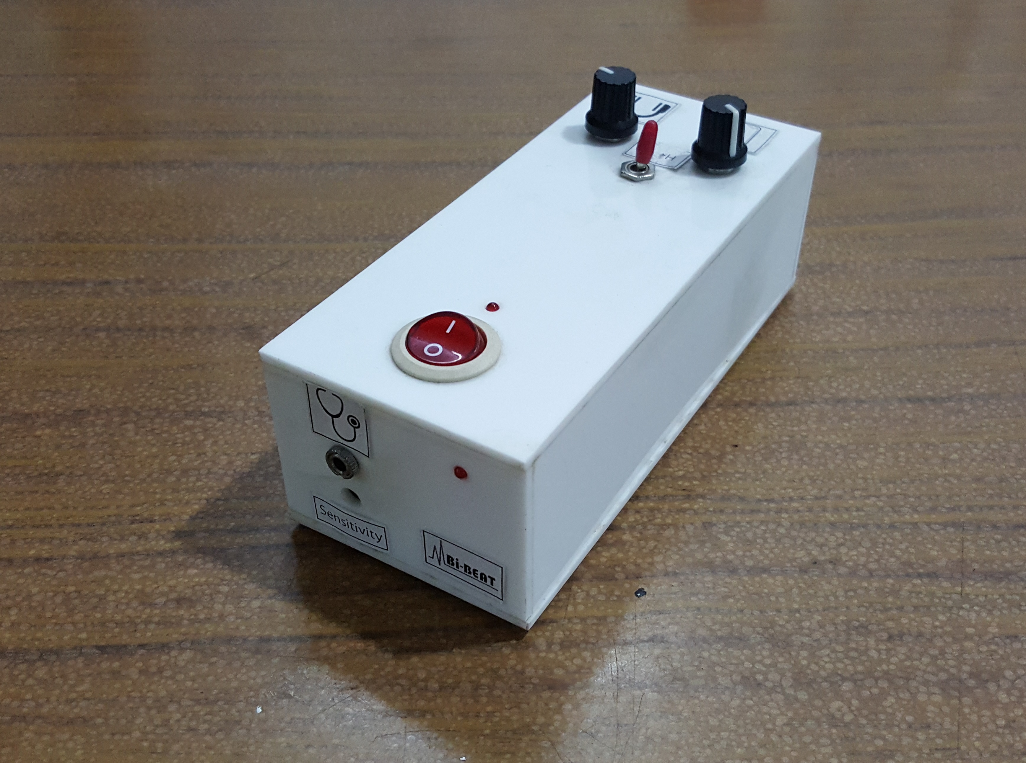
Completed Prototype:
The prototype of the Electronic Stethoscope Device.
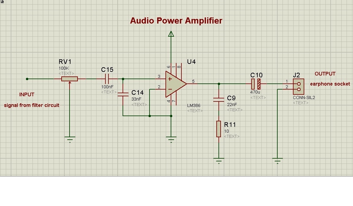
The first stage of the electronic stethoscope circuit was Pre-amplifier and at the second stage filter circuits. In both the stages, op-amp LM358 was used to perform the amplification and filter task. We were supposed to connect an earphone socket at the end of the filter output so that we can insert an earphone to hear the stethoscope sound. But LM358 op-amp can’t provide enough power to drive the earphone. The reason we find is the impedance mismatch between op-amp output impedance and earphone impedance.According to maximum power transfer theorem, maximum power is achieved when the source impedance (here output impedance of the op-amp) is equal to the load impedance (earphone impedance). Since the output impedance of an op-amp is low so it can’t provide enough power to the high impedance earphone (typically, mobile earphone 16Ω to 32Ωand speaker 300 to 600Ω ). To solve this problem, We chose to use an IC name LM386 which is a low voltage audio power amplifier. And it is the 3rd stage of our electronic stethoscope circuit. For this stage, the circuit we designed was based on an example given in the datasheet.

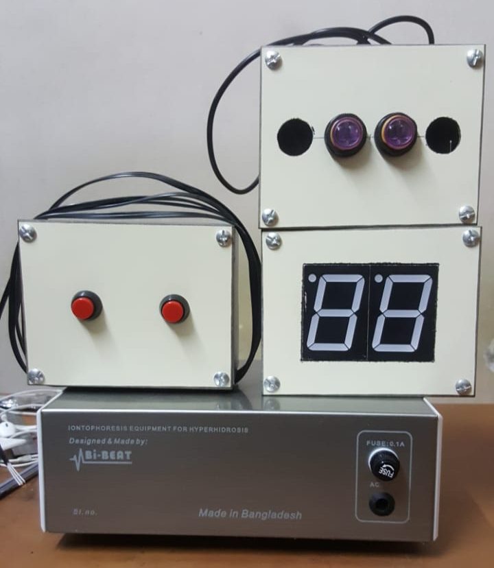
 (Ignore the level on the box)